Key takeaways
- Most lighting plan symbols are drawn to scale for linear and troffer fixtures, while point sources such as downlights use a small circle with a type tag.
- Shading part of a luminaire symbol is the common way to mark emergency or night-light fixtures that stay on from an emergency circuit or battery.
- On schematics the lamp symbol is a circle with an X under IEC 60617, while IEEE 315 drawings use a circle with a filament loop or color letter.
- A home-run arrow tagged with panel and circuit numbers, such as LP-1 3,5, shows which branch circuit feeds a group of luminaires.
- The lumen method N = (E × A) / (Φ × CU × LLF) estimates fixture counts, for example 21 luminaires for 500 lux in an 80 m² office.
Quick answer: Lighting symbols on an electrical plan show the location and type of each luminaire: a circle for a ceiling or recessed fixture, a circle with a line to the wall for a wall fixture, a scaled rectangle for linear or troffer fixtures, and shading for emergency units. A letter tag links each symbol to the luminaire schedule, and S symbols with dashed lines show switching.
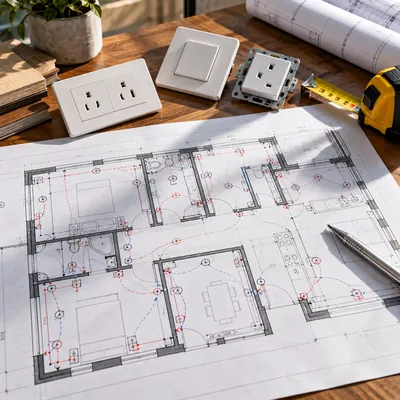
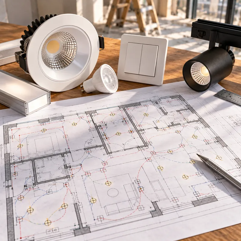
A lighting plan is a reflected ceiling plan with electrical information overlaid. It tells the contractor where each luminaire goes, which type it is, how it is switched and which panel circuit feeds it. All of that is carried by a handful of symbols and tags, and the conventions vary more than most people expect from firm to firm.
This guide is for architects, lighting designers, estimators, electricians and owners reading electrical symbols on floor plans and building plans. It explains the common lighting plan symbols, the lamp symbol used on circuit diagrams, switch and control symbols, circuiting notation, and a worked example that turns a lighting layout into fixture counts and circuit loads. Electrical work in buildings must follow local code and be carried out by a licensed electrician.
What Are Lighting Symbols on an Electrical Plan?
Lighting symbols are the graphic marks on electrical plans that show where luminaires, lighting controls and lighting circuits are located. They are architectural lighting plan symbols, not wiring symbols: they describe position and type, while the internal wiring of a fixture is left to the manufacturer's diagrams.
On most projects the lighting plan is drawn over the reflected ceiling plan, so fixture positions coordinate with ceiling grids, diffusers and sprinklers. Three kinds of information are layered on each symbol:
- Shape, which indicates the mounting and form of the luminaire (point, linear, wall-mounted, pole).
- Type tag, a letter or code (A, B1, L2) that refers to the luminaire schedule listing lumens, wattage, color temperature, voltage and mounting.
- Circuit and control tags, giving the switch leg letter (a, b, c) and branch circuit number.
Plan symbols for electrical work grew out of ANSI Y32.9, which is no longer maintained, so today the project legend is the governing document. IEC-based projects use the installation plan symbols in IEC 60617, which differ in shape. Our overview of electrical symbols and standards explains how plan symbols relate to schematic symbols, and the outlet symbol guide covers the receptacles that share the same sheets on smaller projects.
Lighting Plan Symbols Chart: Common Luminaire Symbols
The chart lists the luminaire symbols most often used on North American electrical symbols for house plans and commercial building plans. Always verify against the project legend.
| Luminaire | How it is usually drawn | Notes |
|---|---|---|
| Ceiling-mounted fixture | Circle, about 1/4 in at plotted scale, with type tag | Surface or pendant; pendant often tagged P |
| Recessed downlight | Smaller circle, often inside a square or with a concentric inner circle | Aperture size and trim in schedule |
| Wall-mounted fixture (sconce) | Circle or semicircle with a short line to the wall | Mounting height noted |
| Linear / strip fixture | Narrow rectangle drawn to scale length | Continuous runs drawn end to end |
| Troffer (2x2, 2x4, 1x4) | Rectangle drawn to scale in the ceiling grid, sometimes with diagonal | Recessed in lay-in ceiling |
| Emergency fixture | Normal symbol with part or all of it shaded | Fed from emergency circuit or with battery |
| Night light | Symbol half shaded, tagged NL | Unswitched, always on |
| Exit sign | Small rectangle or circle with shaded faces and direction arrows | Shaded faces show illuminated sides |
| Emergency battery unit | Rectangle with two small lamp heads | Tagged EM |
| Track lighting | Line with small circles or triangles for heads | Track length to scale |
| Site / pole light | Circle or square on a stem, with arm direction | Shown on site plan |
The recessed light symbol and recessed downlight symbol vary most between firms; some draw a circle with diagonal hatching, others a circle with the letter R. If two symbols on a sheet look alike, the type tag and schedule resolve the difference.
Light Bulb Electrical Symbol in Circuit Diagrams
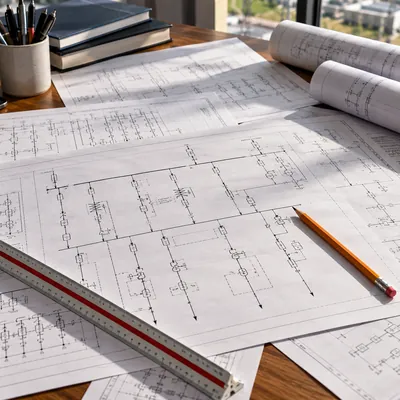
The lamp on a schematic is a different symbol from the luminaire on a plan. The circuit symbol for a lamp represents the electrical load or indicator, not its mounting.
| Symbol | How it is drawn | Standard |
|---|---|---|
| Lamp, general (IEC) | Circle with an X (two diagonals) inside | IEC 60617 |
| Incandescent lamp (IEEE) | Circle containing a looped filament between two terminals | IEEE 315 |
| Indicating / pilot lamp (NEMA ladder) | Circle with radiating short lines, or circle with color letter R, G, A, W, B | NEMA ICS practice |
| Light-emitting diode | Diode triangle and bar inside a circle, with two arrows pointing outward | IEC and IEEE |
| Fluorescent lamp (IEC plan) | Long line with short perpendicular ticks at each end | IEC 60617 installation plans |
| Luminaire outlet (IEC plan) | Line ending in a cross, or circle with X at the outlet point | IEC 60617 installation plans |
In a simple bulb circuit, the lamp symbol sits in series with a switch and a source. In switchgear control schematics, pilot lamps are wired across a breaker auxiliary contact so a red lamp shows closed and a green lamp shows open, the standard North American convention; IEC practice often reverses the colors, so the legend matters. Basic component symbols such as resistors and LEDs are covered in our basic component symbols guide.
Switch and Lighting Control Symbols on Floor Plans
Lighting controls on plans use letter-based symbols, linked to luminaires by curved dashed lines or by matching lowercase switch-leg letters.
- S: single-pole switch.
- S3 / S4: three-way and four-way switches for multi-location control.
- SD: dimmer, with dimming protocol (phase, 0-10 V, DALI) in the schedule.
- SOS, OS or OC: occupancy or vacancy sensor, wall or ceiling mounted; ceiling sensors are often a circle with OS and a dashed coverage outline.
- PC: photocell for daylight or exterior control.
- SLV: low-voltage switch station feeding a lighting control panel.
- TC: time clock, usually located near the panel.
The floor plan light switch symbol carries a lowercase letter, for example S with subscript a (Sa), and every luminaire with the letter a on that plan is controlled by it. This avoids clutter from dashed lines in open-plan areas.
Energy codes in many jurisdictions require automatic shutoff, occupancy sensing and daylight-responsive controls in commercial spaces, so modern lighting plans often show more sensor and control symbols than switches. A control intent narrative or sequence of operations should accompany the plan so the commissioning agent knows how each zone is supposed to behave. The detailed contact arrangement of three-way and four-way switches is explained in the switch and relay symbols guide.
Circuiting Notation: Home Runs and Panel References
Lighting plans tie each fixture to a branch circuit so the contractor can wire it and the panel schedule can be checked.
- Branch wiring is drawn as a curved or straight line between fixtures; concealed wiring in ceilings or walls is a solid line, wiring below floor is dashed.
- Conductor tick marks across the line show the number of conductors: short ticks for current-carrying conductors, a longer tick for the neutral and sometimes a tick with a dot for the ground. Many projects omit ticks and specify minimum conductors in notes.
- Home-run arrow: an arrowhead at the end of a circuit line marks the run back to the panel, tagged with panel name and circuit numbers, for example
LP-1 3,5for two circuits from panel LP-1. - Panel symbol: a rectangle, often filled for flush-mounted panels and open for surface-mounted, labeled with the panel name.
Abbreviations such as LP (lighting panel), EM (emergency), NL (night light), WP and AFF (above finished floor) appear constantly on lighting plans; our electrical abbreviations list decodes them. Each home-run tag must match a line on the panel schedule, where the connected VA of the fixtures on that circuit is entered. Commercial lighting is frequently fed at 277 V from a 480Y/277 V system, which reduces current and voltage drop; the 277/480 V system guide explains why.
Worked Example: From Lighting Layout to Fixture Count and Circuit Load
The lumen method gives a quick check that the number of symbols on a lighting plan delivers the target illuminance.
N = (E × A) / (Φ × CU × LLF)
where N is the number of luminaires, E the target maintained illuminance (lux), A the area (m²), Φ the luminaire lumen output, CU the coefficient of utilization and LLF the light loss factor.
Office example
- Room 10 m × 8 m, so
A = 80 m² - Target 500 lux (about 46 footcandles)
- LED panel 4,000 lm, 36 W; CU 0.60; LLF 0.80
N = (500 × 80) / (4,000 × 0.60 × 0.80) = 40,000 / 1,920 ≈ 20.8
Round to 21 and then fit to the ceiling grid, typically a 4 × 5 or 4 × 6 array. With 24 fixtures the maintained level is about 500 × 24 / 20.8 ≈ 577 lux.
Circuit load
Connected load: 24 × 36 W = 864 W. Treating lighting as a continuous load, a 277 V, 20 A branch circuit may be loaded to 80%:
277 V × 20 A × 0.80 = 4,432 VA
One circuit is ample for the room, and in practice the designer splits it into two switch zones (window row on daylight control). The lighting power density is 864 W / 80 m² ≈ 10.8 W/m², a figure to check against the applicable energy code.
Next Steps: From Lighting Plans to Distribution Equipment
Lighting plans feed the panel schedules, and panel schedules feed the distribution design. To carry lighting loads correctly into equipment specifications:
- Total connected and demand lighting load per panel, separating normal and emergency circuits.
- Decide distribution voltage: 277 V lighting from a 480Y/277 V system, or 230 V from a 400/230 V system, with dry-type step-down transformers for 120 V or 208 V loads.
- Specify LV switchboard incomers, feeders to lighting panels and any lighting control panels.
- For emergency lighting, define the source: central inverter, generator via transfer switch, or battery units in fixtures.
MARS does not make luminaires or lighting controls. We manufacture IEC 61439 LV switchboards (GGD, GCS, MNS), MV switchgear and cast-resin dry-type transformers that supply building lighting and power distribution. See the HV and LV switchgear range or the dry-type transformer range, and send your load schedule through the quote request form.
Frequently asked questions
What is the symbol for a recessed light on a floor plan?
A recessed light or downlight is usually drawn as a small circle, often inside a square or with a smaller concentric circle, and tagged with a letter that refers to the luminaire schedule. Some firms add the letter R or diagonal hatching. Because practice varies, the project legend sheet defines the exact recessed downlight symbol.
What is the electrical symbol for a light bulb?
On IEC 60617 schematics a lamp is a circle with an X inside. IEEE 315 drawings may show a circle containing a looped filament, and NEMA control diagrams show pilot lamps as a circle with radiating lines or a color letter such as R or G. On floor plans, luminaires use different location symbols.
How are emergency lights shown on electrical plans?
Emergency luminaires are normally drawn with the same symbol as the normal fixture but with part or all of the symbol shaded, and are tagged EM. Battery emergency units are often drawn as a rectangle with two lamp heads. Exit signs are small rectangles or circles with shaded faces and arrows showing direction.
What do letters next to light symbols mean?
An uppercase letter or code beside a light symbol, such as A or B2, is the luminaire type and refers to the fixture schedule. A lowercase letter, such as a or b, is the switch leg, matching a switch marked with the same letter. Numbers near a home-run arrow give the panel circuit.
How many lights can be on one circuit?
The limit comes from load, not count. Lighting is treated as continuous, so a branch circuit is loaded to 80% of its rating: 1,920 VA on a 120 V 20 A circuit or 4,432 VA on a 277 V 20 A circuit. Divide by each fixture's input VA and allow for voltage drop and control zoning.
What symbols are used for lighting on IEC drawings?
IEC 60617 installation plans show a luminaire outlet as a cross at the end of a line or a circle with an X, a fluorescent luminaire as a long bar with short ticks at each end, and emergency luminaires with an additional marking. Switches use a small circle with an angled stroke, rather than the North American letter S.
Written and reviewed by the MARS application engineering team in Shanghai, who specify and test transformers, switchgear, substations and battery storage for projects in 40+ countries. Last updated .
Tags: lighting symbols plan symbols for electrical recessed light symbol electrical symbols on floor plans light bulb electrical symbol