Key takeaways
- A 3 phase pad mounted transformer steps down medium-voltage distribution (4.16 kV to 34.5 kV) to commercial secondary voltages (480Y/277 V or 208Y/120 V) within a lockable, tamper-resistant cabinet.
- Dead-front terminal arrangements with 200 A loadbreak or 600 A deadbreak separable insulated connectors provide operator safety by fully enclosing all energized conductors.
- Loop-feed designs feature six high-voltage bushings and internal four-position sectionalising switches, allowing continuous service during downstream cable maintenance or fault isolation.
- Enclosures must comply with IEEE C57.12.28 or IEEE C57.12.29 tamper-resistance standards to permit safe installation in public-access locations without security fencing.
- Standard protection incorporates dual-element expulsion Bay-O-Net fuses in series with partial-range current-limiting back-up fuses to manage low overload currents and high fault energies up to 50 kA.
Quick answer: A 3 phase pad mounted transformer is a tamper-resistant, liquid-immersed distribution transformer installed at ground level on a concrete pad, stepping down underground medium-voltage feeds (4.16 kV to 34.5 kV) to low utilisation voltages (typically 480Y/277 V or 208Y/120 V) for commercial, utility, and industrial facilities.
As modern urban and industrial developments transition from overhead distribution lines to underground medium-voltage networks, the three phase pad mounted transformer has become the cornerstone of commercial power distribution. Unlike overhead pole-top units or indoor vault transformers, pad-mounted equipment integrates the transformer core-coil assembly, fluid preservation system, and separated high- and low-voltage cable compartments into a single, weather-sealed, tamper-resistant enclosure. This compact, self-contained architecture eliminates the need for expensive indoor substations or protective perimeter fencing, allowing close siting adjacent to commercial buildings, factories, and utility right-of-ways.
Selecting the correct three phase pad mounted transformer requires balancing electrical parameters such as rated capacity (kVA), primary basic impulse insulation level (BIL), and secondary fault levels against operational requirements, including radial versus loop-feed switching, overcurrent protection coordination, and environmental containment. For a broader overview of three-phase transformation principles, consult our comprehensive 3 phase transformer guide.
Core Engineering: What is a Three Phase Pad Mounted Transformer?
A three phase pad mounted transformer consists of an oil-filled tank containing the magnetic core and windings, integrated with a compartmentalised front terminal enclosure divided into distinct high-voltage (HV) and low-voltage (LV) sections. The design is engineered strictly for underground cable entry through an open bottom that mounts directly over a concrete foundation pad or prefabricated vault.
The unit relies on mineral oil or less-flammable natural ester fluid (such as FR3, governed by ASTM D6871) for dielectric insulation and thermal dissipation. Winding arrangements commonly employ a five-legged wound core or stacked-core configuration using high-permeability, grain-oriented silicon steel. To manage third-harmonic currents, prevent ferroresonance, and mitigate secondary phase displacement, engineers typically specify a Delta primary with a grounded Wye secondary (Dyn1 or Dyn11 under IEC conventions; ANSI/IEEE standard 30-degree phase displacement). You can explore winding topologies in depth through our guide on the delta wye transformer diagram.
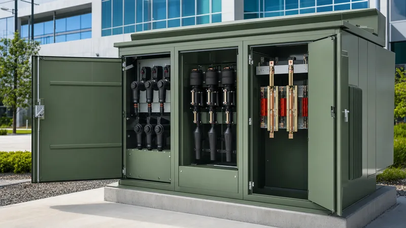
Front compartments are physically segregated by a full-height steel barrier. The LV compartment contains spade-type bushings (ranging from 4-hole to 16-hole NEMA arrangements) engineered to handle secondary currents exceeding 4,000 A at lower voltages. The HV compartment houses medium-voltage bushings, sectionalising loadbreak switches, and internal protective fusing. Under IEEE C57.12.34, access is sequentially interlocked: the high-voltage door cannot be released until the low-voltage door is unlocked and opened, ensuring technicians can verify isolation before approaching medium-voltage components.
Radial Feed vs Loop Feed Bushing Configurations
The choice between radial-feed and loop-feed configurations determines how a 3 phase pad mounted transformer integrates into the primary medium-voltage utility distribution network. While radial configurations serve single, dead-ended loads, loop configurations provide utility redundancy by integrating each unit into a continuous medium-voltage ring circuit.
A radial-feed unit features three high-voltage bushings (H1, H2, H3). It terminates an underground medium-voltage lateral run, making it cost-effective for single-facility sites where service interruptions during cable maintenance are permissible. In contrast, a loop-feed transformer incorporates six high-voltage bushings grouped as incoming and outgoing sets (H1A, H2A, H3A and H1B, H2B, H3B). This arrangement allows utility power to pass through the cabinet to downstream transformers in a daisy-chain configuration.
Loop-feed systems normally incorporate an internal, oil-immersed, four-position sectionalising switch (often designated as a radial/loop or T-blade switch). This switch allows maintenance teams to execute four distinct switching states without disconnecting high-voltage cables: feed from circuit A only, feed from circuit B only, feed from both circuits simultaneously, or isolate the transformer windings entirely while maintaining cable continuity between loop legs A and B. For complex distribution networks, compare these configurations with our breakdown of distribution transformer types, sizing, and specs.
Technical Comparison: Radial vs Loop Feed Specifications
A direct specification comparison highlights the engineering trade-offs between radial-feed and loop-feed pad-mounted transformers across standard parameters defined by IEEE C57.12.34 and CSA C227.4.
| Engineering Metric | Radial Feed Configuration | Loop Feed Configuration |
|---|---|---|
| HV Bushing Count | 3 bushings (H1, H2, H3) | 6 bushings (H1A–H3A, H1B–H3B) |
| Switching Capability | External circuit disconnect or on/off switch | Internal 4-position rotary loadbreak switch (300 A or 600 A) |
| System Redundancy | None; outage on lateral isolates transformer | Full dual-feed redundancy; open-loop or closed-loop operation |
| Typical Ratings (kVA) | 75 kVA to 1,500 kVA | 150 kVA to 5,000 kVA |
| Primary Voltages | 2.4 kV through 34.5 kV GrdY | 4.16 kV GrdY through 34.5 kV GrdY |
| BIL Rating | 60 kV to 150 kV | 60 kV to 150 kV (170 kV optional) |
| Cable Termination Type | 200 A loadbreak wells or 600 A deadbreak | 200 A loadbreak wells/inserts or 600 A apparatus bushings |
| Application Focus | Dedicated industrial plants, small sites | Commercial campuses, data centres, utility underground rings |
Protection Schemes: Bay-O-Net Fuses and Current-Limiting Fuses
Primary overcurrent protection inside a 3 phase pad mounted transformer relies on a coordinated two-part system designed to clear both thermal overloads and catastrophic high-current internal faults safely within the liquid-immersed environment.
- Expulsion Fusing (Bay-O-Net): The first line of defense is an externally replaceable, oil-immersed Bay-O-Net fuse assembly located in the high-voltage compartment. Utilizing dual-element or current-sensing fuse links, the Bay-O-Net fuse detects secondary distribution faults, long-term transformer overloads, and elevated fluid temperatures. Technicians can replace these fuses safely in the field using a standard insulated hotstick after releasing internal tank pressure.
- Back-up Current-Limiting Fuses (ELSP): Connected in series with each Bay-O-Net assembly is an internal, partial-range current-limiting fuse (such as an ELSP). This fuse remains inactive during low-magnitude overloads but operates rapidly when high-current fault events occur (typically above 1,500 A to 3,000 A). By clipping the peak fault current and forcing zero-crossing extinction within a quarter of a cycle, the ELSP limits let-through energy ($I^2t$) to under 100,000 $A^2s$, preventing violent tank rupture from energy release during a primary winding breakdown.
- Under-Oil Surge Arresters: For circuits subject to switching surges or lightning impulses along underground-to-overhead riser poles, internal or elbow-mounted metal-oxide varistor (MOV) surge arresters are integrated directly onto the 200 A bushing inserts to limit transient overvoltages below the transformer BIL rating.
Enclosure Security, Pad Clearances, and Siting Standards
Physical security and clearance requirements for a three phase pad mounted transformer are governed by rigorous standards to protect the public and facilitate safe operational servicing. Because these units are accessible in open parking lots, commercial courtyards, and residential areas, enclosures are constructed to meet IEEE C57.12.28 (standard steel) or IEEE C57.12.29 (coastal/corrosive environments).
Cabinet security features include recessed padlock hasps, penta-head captive security bolts requiring specialised utility wrenches, continuous hood hinges, and overlapping door flanges designed to resist mechanical pry-bar testing exceeding 400 Nm of applied torque. Labyrinth baffle designs at all cooling louvres prevent intentional wire insertion into energized compartments. For further structural housing details, read our guide on electrical transformer box engineering and siting.
Siting clearances must comply with the National Electrical Code (NEC Article 450) and local utility standards. Maintain the following mandatory working and safety boundaries:
- Front Door Clearances: A minimum of 3.0 metres (10 feet) of unobstructed, clear space directly in front of the compartment doors to allow utility technicians to safely handle medium-voltage elbows using a 2.4-metre hotstick.
- Side and Rear Clearances: A minimum of 0.9 to 1.2 metres (3 to 4 feet) from combustible exterior building walls, overhangs, windows, and fire escapes. If non-combustible materials are present, clearances may reduce to 0.6 metres, provided cooling airflow is unhindered.
- Oil Containment: Units holding more than 1,890 litres (500 US gallons) of conventional mineral oil require an external oil containment curb, retaining pit, or the specification of less-flammable ester fluid with a fire point exceeding 300°C per NEC 450.23.
Step-by-Step Procedure for Transformer Installation and Pre-Commissioning
Commissioning a 3 phase pad mounted transformer demands systematic mechanical and electrical verification before energisation to prevent equipment damage and safeguard site personnel.
- Foundation Verification: Confirm the poured concrete pad is fully cured (minimum 28-day compressive strength of 20 to 25 MPa) and level within a tolerance of 3 mm per metre. Verify the conduit window aligns precisely with the transformer high-voltage and low-voltage compartment bottom openings without structural interference.
- Rigging and Placement: Hoist the unit using the four factory-welded lifting lugs located on the tank walls, maintaining a rigging sling angle of at least 60 degrees from the horizontal to avoid crushing the cabinet top. Carefully lower the unit onto the pad, ensuring the base-channel sill sits flush over the conduit perimeter.
- Tank Grounding: Bond the transformer grounding pads immediately to the primary substation or site earth grid using bare stranded copper conductor (minimum 50 mm² or 1/0 AWG), ensuring ground loop resistance tests below 5 ohms per IEEE 80 guidelines.
- Insulation and Winding Testing: Execute an insulation resistance test (Megger) at 2.5 kV or 5 kV DC between windings and ground, followed by a Transformer Turns Ratio (TTR) test across all de-energised tap changer positions to confirm voltage ratios match factory certified test reports within ±0.5%.
- Pressure and Fluid Inspection: Verify the internal pressure-vacuum gauge reads normal, operate the manual pressure relief valve to vent shipping pressure, and verify dielectric breakdown voltage of the liquid meets IEC 60156 or ASTM D877 standards (minimum 30 kV).
- Elbow Termination and Latching: Terminate medium-voltage cables using certified 200 A loadbreak or 600 A deadbreak elbow kits. Clean, lubricate with silicone, and fully seat each elbow onto its bushing insert, verifying the mechanical locking indicator is engaged.
Next steps: specifying and sourcing
When preparing an inquiry or Request for Quotation (RFQ) for a 3 phase pad mounted transformer, precise operational data ensures factory engineering teams deliver an optimized design. Prepare your system capacity (kVA), primary medium-voltage level and BIL rating, secondary utilization voltage, dead-front bushing preference (radial or loop feed), impedance range (%Z), and preferred insulating fluid (standard mineral oil or high-fire-point natural ester).
Explore our heavy-duty pad mounted transformer solutions and broad range of oil immersed transformer systems engineered to IEEE and IEC standards. To review customized electrical configurations, dimensions, and manufacturing lead times for your project, submit your specifications directly through our transformer quotation portal.
Frequently asked questions
What is the difference between dead-front and live-front pad mounted transformers?
A dead-front transformer encloses all primary terminations inside fully shielded, insulated, separable rubber elbow connectors, exposing no live high-voltage parts when the cabinet is open. A live-front transformer uses exposed porcelain bushings with open mechanical spade or stud terminals, requiring technicians to de-energise and ground the entire primary circuit before servicing.
What is the typical lifespan of a 3 phase pad mounted transformer?
The operational design life of a three phase pad mounted transformer is typically 30 to 40 years under normal operating conditions. Longevity depends heavily on operating temperatures, loading profiles below thermal limits, regular inspection of cabinet corrosion, and maintaining dielectric fluid quality through periodic moisture and gas testing.
Why is a loop feed pad mounted transformer preferred for commercial campuses?
Loop feed transformers allow multiple buildings to be connected in a continuous medium-voltage ring fed from two independent utility points. If a cable segment faults or requires planned maintenance, internal sectionalising switches allow technicians to isolate that specific cable while keeping all transformers along the rest of the loop energised.
What voltages are standard for three phase pad mounted transformers?
Primary distribution voltages typically range from 4,160 GrdY/2,400 V up to 34,500 GrdY/19,920 V. Standard commercial secondary utilization voltages are 480Y/277 V (for commercial HVAC and industrial motor loads) and 208Y/120 V (for light commercial and institutional power circuits).
Can a pad mounted transformer be installed indoors?
Yes, a pad mounted transformer can be installed indoors provided it meets National Electrical Code (NEC) requirements regarding fire-rated electrical vaults, liquid containment, and ventilation. Many engineers specify natural ester fluid (less-flammable liquid) to reduce structural vault construction requirements when placing these units inside commercial buildings.
Tags: 3 phase pad mounted transformer three phase pad mounted transformer pad mounted transformer specs loop feed transformer underground power distribution


