Key takeaways
- A low voltage landscape lighting transformer steps down mains supply (120 V or 230 V) to an isolated extra-low voltage (12 V to 15 V AC) to power exterior luminaires safely.
- Selecting secondary multi-tap terminals (12 V, 13 V, 14 V, and 15 V) is essential to compensate for line conductor voltage drop across extended outdoor cable runs.
- Total transformer capacity must account for luminaire apparent power (volt-amperes) and driver power factors, maintaining an operational load between 70% and 85% of rated capacity.
- Compliance with standards such as UL 1838, NEC Article 411, and IEC 61558-2-6 ensures full galvanic isolation, thermal protection, and earth-fault safety in damp outdoor environments.
- Integrated magnetic circuit breakers and Class H (180°C) insulation provide the highest operational reliability against outdoor moisture ingress and LED high-inrush currents.
Quick answer: A low voltage landscape lighting transformer is an outdoor-rated, step-down safety isolating unit that converts commercial or domestic mains supply (120 V or 230 V AC) to safe extra-low voltage (typically 12 V to 15 V AC). It isolates secondary circuits from mains earth, manages cable voltage drop through multi-tap outputs, and shields exterior lighting systems against overloads.
Exterior architectural and municipal illumination systems depend on safe, stable power delivery under severe environmental conditions. Whether supplying ground luminaires, pathway floodlights, or architectural accents, a low voltage lighting transformer serves as the fundamental power conversion barrier between high-voltage utility distribution and accessible public areas. In commercial sites, municipal plazas, and high-end residential spaces, specifying the correct 12v landscape lighting transformer requires strict adherence to conductor sizing, volt-drop mitigation, and thermal design to prevent premature luminaire failure or fire hazards.
How a Low Voltage Landscape Lighting Transformer Operates
A low voltage landscape lighting transformer operates on the principle of electromagnetic induction via two magnetically coupled, galvanically separated windings wound around a laminated steel or toroidal core. The primary winding connects to the 120 V or 230 V AC supply, establishing an alternating magnetic flux that induces a reduced potential in the secondary winding, producing a stable extra-low voltage output complying with IEC 61558-2-6 clause 8.1 for safety isolating units.
Unlike indoor control units, an outdoor low voltage transformer features specialised engineering provisions:
- Galvanic isolation: Physical separation and high-dielectric insulation barriers between primary and secondary coils prevent mains fault voltages from energising the secondary landscape circuits.
- Electrostatic shielding: Grounded copper shielding placed between windings shunts high-frequency grid transients and surges directly to earth.
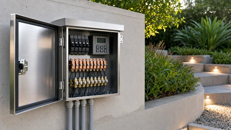
- Multi-tap output lugs: Secondary windings feature discrete tap outputs (typically 12 V, 13 V, 14 V, and 15 V) allowing electrical engineers to offset resistance losses across extended outdoor cable loops.
- Core design: High-permeability silicon steel laminations minimise hysteresis and eddy current losses, which is critical when managing continuous evening duty cycles. For single-phase system dynamics, review our single-phase transformer design guide.
Sizing Calculations and Cable Voltage Drop Compensation
Calculating the required capacity of a low voltage outdoor landscape lighting transformer requires determining total connected load in volt-amperes (VA) while accounting for conductor impedance and LED driver power factor. Operating a landscape low voltage transformer beyond 85% of its rated nameplate capacity accelerates thermal degradation and nuisance-trips internal magnetic breakers.
When deploying modern LED fixtures, calculating purely in nominal watts causes severe under-sizing because LED drivers frequently exhibit a power factor (PF) between 0.65 and 0.85. The nominal wattage must therefore be converted to apparent power:
Apparent Power (VA) = Total Fixture Wattage (W) / Power Factor (PF)
To calculate voltage drop along a run of two-conductor copper cable, apply Ohm's law tailored to loop conductor distance:
V_drop = (2 × L × I × R) / 1000
Where L is one-way run length in metres or feet, I is total circuit current in amperes, and R is conductor resistance in ohms per thousand units of length according to national electrical standards.
Worked Engineering Example:
Consider an outdoor commercial path illumination circuit consisting of 12 LED bollards consuming 10 W each (120 W total) with a driver power factor of 0.80. The run measures 50 metres (164 feet) from the outdoor transformer to the terminal load using 12 AWG stranded copper cable, which exhibits an electrical resistance of 5.31 ohms per 1,000 metres (1.62 ohms per 1,000 feet).
- Calculate Apparent Power: 120 W / 0.80 PF = 150 VA.
- Determine Nominal Current at 12 V: I = 150 VA / 12 V = 12.5 A.
- Calculate Loop Voltage Drop: V_drop = (2 × 50 m × 12.5 A × 5.31 Ω/km) / 1000 = 6.64 V.
- Evaluate Terminal Voltage: 12.0 V - 6.64 V = 5.36 V.
An operating voltage of 5.36 V at the final luminaire causes LED driver shutdown, excessive current draw, or severe optical flicker. To rectify this, the engineer selects the 15 V secondary tap on the 12v landscape transformer and splits the line into two parallel 'T-fed' or loop runs of 6.25 A each. Recalculating with a 6.25 A load reduces the voltage drop to 3.32 V, delivering a stable 11.68 V at the final terminal—comfortably within standard operating specifications (10.8 V to 12.5 V AC).
Magnetic vs Electronic 12V Landscape Lighting Transformer Comparison
A magnetic low voltage lighting transformer uses iron-core wire-wound assemblies, whereas an electronic volt transformer uses high-frequency solid-state switching circuits to achieve step-down conversion. In demanding municipal, commercial, and landscape installations, magnetic architecture remains the standard choice due to physical robustness and high fault endurance.
| Engineering Parameter | Magnetic Transformer | Electronic Power Supply |
|---|---|---|
| Primary Core Technology | Laminated silicon steel or toroidal core | Solid-state high-frequency inverter switch |
| Output Voltage Frequency | 50 Hz / 60 Hz sinusoidal | 20 kHz to 50 kHz high frequency |
| Maximum Cable Run Distance | Up to 90 m (with 15 V tap compensation) | Restricted to < 15 m (high RF attenuation) |
| LED Inrush Current Handling | Exceptional (tolerates up to 10× for 50 ms) | Limited (fast internal overload shutdown) |
| Operating Lifespan (B10) | 20+ years (vacuum-potted resin) | 5 to 8 years (electrolyte dry-out risk) |
| Environmental Enclosure | 304/316 Stainless Steel, IP65 / NEMA 3R | Anodised aluminium or plastic, IP54 / IP67 |
| Secondary Voltage Adjustment | Multi-tap terminal rail (12 V to 15 V) | Fixed single voltage or internal potentiometer |
Electronic power units present distinct disadvantages over long cable runs because high-frequency currents suffer severe inductive reactance losses and generate radio frequency interference. Consequently, industrial specifications for garden lights low voltage transformer units require magnetic construction paired with stainless steel housings.
Protection Systems and Landscape Lighting Control Systems
Protection systems within a low voltage outdoor light transformer prevent equipment destruction caused by downstream short circuits, insulation degradation, and earth faults. In contrast to standard distribution units, outdoor landscape lighting transformer installations are exposed to direct moisture, soil chemical exposure, ground settling, and physical damage from garden tools.
To guarantee complete electrical protection under NEC Article 411 and IEC 60364-7-714, industrial-grade units integrate three distinct defence mechanisms:
- Secondary Magnetic Circuit Breakers: Unlike standard thermal breakers that trip slowly under moderate continuous overloads, magnetic breakers trip instantaneously upon sensing severe fault currents, protecting extra-low-voltage runs against overheating. Learn more about system coordination in our transformer protection guide.
- Thermal Cut-Off Integration: Sealed inside the primary windings, automatic-reset thermal switches isolate primary power if the core temperature exceeds safe insulation limits (typically Class H, 180°C).
- Landscape lighting control systems integration: Contemporary outdoor installations incorporate modular micro-controllers, smart low voltage transformer automation, photocell optical sensors, and astronomical timers. Connecting these controls to the primary coil circuit eliminates standby core losses during daylight hours.
Step-by-Step Installation and Commissioning Procedure
Installing and commissioning an outdoor lighting transformers 12v assembly requires methodical verification of line power, grounding integrity, tap terminations, and operational secondary voltages. Adhering to the following procedure ensures compliance with regional wiring standards and maximises luminaire operational life.
- Mounting and Physical Siting: Secure the stainless steel enclosure vertically to a non-combustible structural wall or concrete pedestal at least 300 mm (12 inches) above finished ground level to prevent flood water ingress and snow cover.
- Primary Mains Connection: Terminate the high-voltage supply through dedicated rigid conduit into the primary wiring compartment. Ensure bonding to the protective earth (PE) terminal stud in accordance with IEC 61439 low-voltage standards.
- Cable Insulation Testing: Before connecting field cables to the secondary terminals, conduct a 500 V DC insulation resistance test on all buried field lines using an insulation tester, ensuring readings exceed 50 megohms to earth. Detailed test parameters are available in our transformer testing guide.
- Secondary Circuit Termination: Strip the low-voltage secondary cables cleanly and torque them securely into the screw-clamp terminal lugs. Connect the common conductor to the 'COM' terminal and the phase conductor to the 12 V tap for baseline commissioning.
- Energisation and Voltage Balancing: Energise the primary supply and measure line voltage at each luminaire terminal using a True-RMS multimeter under full load conditions. If terminal voltage at distant fittings falls below 11.0 V, shift that circuit's conductor at the transformer panel to the 13 V, 14 V, or 15 V tap until terminal voltages sit securely between 11.2 V and 12.0 V AC.
- Operational Current Verification: Measure individual secondary circuit load current using a calibrated clamp meter. Confirm that measured currents do not exceed 80% of the individual circuit breaker trip rating.
Technical Specification Checklist for B2B Procurement
When preparing procurement specifications for an industrial, commercial, or municipal low voltage led transformer, specifying engineers should outline precise electrical and mechanical parameters to guarantee supply chain consistency and long-term durability.
Include the following core engineering requirements within your request for proposal (RFP) documentation:
- Core Construction: Grain-oriented silicon steel (M4 or better) or high-efficiency toroidal core vacuum-impregnated with epoxy resin for acoustic attenuation (< 40 dBA) and corrosion resistance.
- Rated Apparent Power: Standard steps (300 VA, 600 VA, 900 VA, or 1,200 VA) equipped with split, independently breakered secondary circuits (e.g., 4 × 300 VA secondary banks).
- Secondary Tap Range: Minimum four-stage stepped terminals: 12 V, 13 V, 14 V, and 15 V AC.
- Enclosure Rating: Grade 304 or marine-grade 316 stainless steel housing with a lockable hinged door, rated to minimum IP65 or NEMA 3R/4X.
- Winding Material: 100% high-conductivity electrolytic copper windings with Class H (180°C) or Class 200 insulation ratings.
- Testing & Standards Compliance: Certified to UL 1838, CSA C22.2 No. 250.7, and IEC 61558-2-6, including dielectric withstand proof testing at 2,500 V primary-to-secondary.
Next steps: specifying and sourcing
Selecting the optimal low voltage landscape lighting transformer requires balancing system load capacity, cable topologies, and thermal environmental constraints. If you are developing commercial landscape plans, municipal infrastructure, or industrial perimeter lighting schemes, our engineering team can review your single-line diagrams, volt-drop calculations, and tap requirements to propose fully compliant step-down units. Discover our complete line of industrial step-down and distribution products on our dry-type transformer page and integrated transformer substation page. For tailored quotations, schedule an engineering consultation via our contact page or submit your technical schedule directly through our quote request page.
Frequently asked questions
What size low voltage landscape lighting transformer do I need?
Calculate the total wattage of all connected luminaires, divide by the driver power factor (typically 0.8 for LEDs) to obtain total volt-amperes, and add a 20% safety margin. For example, a 160 W LED load requires approximately 200 VA; selecting a 300 VA transformer ensures safe, long-term operation without thermal overloading.
Why does a landscape lighting transformer feature 13V, 14V, and 15V taps?
Higher-voltage secondary taps compensate for conductor resistance losses across long distances. As voltage drops over extended cable runs, connecting the supply cable to a 13 V, 14 V, or 15 V tap boosts initial output, ensuring luminaires at the end of the line receive the required 11 V to 12 V.
Can I use an electronic transformer for outdoor low voltage lighting?
Electronic transformers are unsuitable for long outdoor cable runs because their high-frequency output (20 kHz to 50 kHz) induces severe inductive line losses and electromagnetic interference. Magnetic transformers running at 50 Hz or 60 Hz provide the stability and inrush capacity necessary for exterior landscape runs.
How far can I run low voltage wire from an outdoor transformer?
With standard 12 AWG cable and a typical 100 W LED load, maximum run distance is approximately 30 to 45 metres from a 12 V tap. Utilizing 10 AWG copper cable and connecting to a 15 V secondary tap allows operational cable runs to extend up to 90 metres safely.
What is the difference between a low voltage transformer and an LED driver?
A low voltage landscape transformer outputs alternating current (typically 12 V to 15 V AC) through electromagnetic step-down coils. An LED driver typically rectifies AC power into regulated direct current (12 V or 24 V DC constant voltage, or fixed constant current) using solid-state switching circuitry.
Tags: low voltage landscape lighting transformer landscape lighting transformer low voltage transformer outdoor low voltage transformer 12v landscape lighting transformer


