Key takeaways
- A house transformer steps down medium-voltage grid distribution levels (typically 11 kV to 34.5 kV) to domestic utilisation voltages such as 120/240 V split-phase or 230/400 V three-phase.
- Residential underground distribution relies heavily on loop-feed pad-mounted transformers configured in open rings for rapid service restoration.
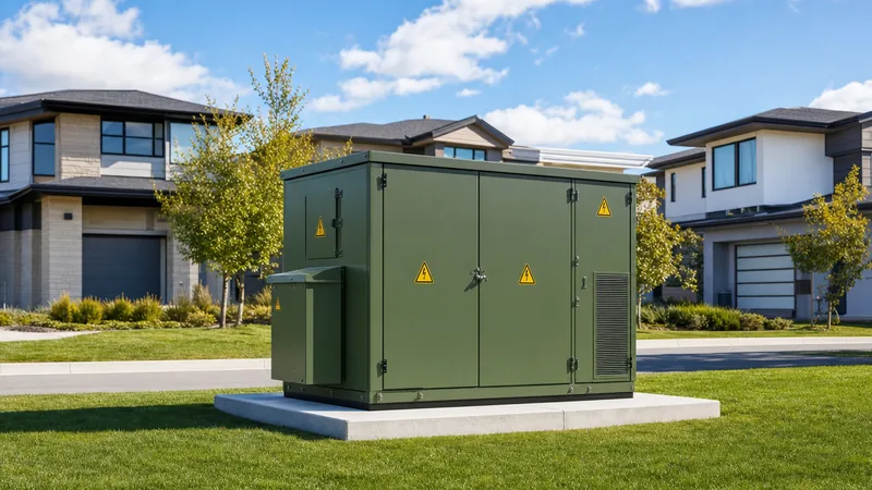
- Overhead pole-mounted transformers provide cost-effective service for low-density housing, whereas compartmental pad-mounted units deliver tamper-resistant underground service for modern estates.
- Accurate transformer sizing requires applying regional diversity and coincidence factors to prevent continuous thermal overload beyond the IEEE C57.91 65 °C average winding rise limit.
- Factory routine testing per IEC 60076-1 and IEEE C57.12.90 verifies winding resistance, no-load losses, load losses, ratio, and dielectric insulation withstand before site energisation.
Quick answer: A house transformer is a medium-voltage distribution transformer that steps down grid utility voltages (such as 11 kV, 13.8 kV, or 24.94 kV) to end-user utilisation levels (such as 120/240 V single-phase or 230/400 V three-phase) to supply residential properties safely and reliably.
In electrical utility networks, delivering power to residential communities involves high-voltage transmission, medium-voltage distribution, and final step-down conversion at the edge of the low-voltage grid. Whether installed overhead on an aerial utility pole or mounted at grade on a concrete plinth in an underground residential distribution (URD) scheme, the house transformer serves as the critical interface between the utility network and the residential service entrance. Selecting the correct architecture depends on feeder topology, housing density, environmental exposure, and local utility regulations. For modern underground layouts, engineers evaluate radial feed vs loop feed topologies to balance upfront capital costs against network reliability and isolation flexibility.
What Is a House Transformer and How Does It Operate?
A house transformer operates on the principle of electromagnetic induction to convert medium-voltage primary distribution power into low-voltage secondary power suitable for domestic domestic branch circuits. Alternating current entering the high-voltage primary winding produces an alternating magnetic flux in the laminated silicon steel or amorphous metal core. This magnetic flux links through the magnetic circuit to induce a proportional electromotive force across the low-voltage secondary winding, governed by Faraday's law and the turn-to-turn ratio.
For detailed winding configurations, consult our technical review on transformer primary and secondary windings. In North American split-phase distribution, the primary winding connects phase-to-neutral or phase-to-phase on an MV system (such as 7,200 V on a 12.47 kV grounded wye feeder), while the secondary winding delivers 240 V across outer legs with a grounded centre tap providing two 120 V legs. In IEC jurisdictions, the secondary delivers a 230/400 V four-wire three-phase arrangement (phase-to-neutral and phase-to-phase) under TN-C-S or TN-S grounding schemes compliant with IEC 60364-1.
Because domestic loads cycle between midday troughs and evening peaks, the transformer core and winding assembly must withstand continuous thermal cycling. Mineral insulating oil or high-fire-point synthetic/natural esters circulate via natural convection (ONAN cooling) through external cooling fins or corrugated tank walls, dissipating copper ($I^2R$) and core hysteresis losses to maintain winding hotspot temperatures below the thermal degradation limits established in IEEE C57.12.00 Table 5 or IEC 60076-2.
Residential Transformer Diagram: Overhead vs Pad-Mounted Architecture
A comprehensive residential transformer diagram reveals distinct physical, mechanical, and protection layouts depending on whether the unit is an overhead pole-mount or an underground pad-mount. Overhead distribution typically relies on cylindrical steel tanks suspended from crossarms or pole bands, connecting to open-wire aerial feeders via porcelain or polymer surge arresters and fused cutouts.
A typical pole transformer diagram illustrates the following core electrical elements:
- High-voltage bushing: Positioned on the tank lid, receiving single-phase MV line voltage through a sacrificial drop-out fuse link (fused cutout) and a metal-oxide varistor (MOV) surge arrester.
- Low-voltage bushings: Three side-mounted stud terminals designated X1, X2 (neutral), and X3 for split-phase 120/240 V service, with X2 solidly bonded to the tank ground and earthing down-lead.
- Core-coil assembly: Immersed in dielectric oil, often equipped with an internal secondary breaker or oil-immersed weak-link fuse in Completely Self-Protected (CSP) designs.
- Lifting lugs and ground pad: Standard mechanical features compliant with IEEE C57.12.20.
Conversely, in modern residential subdivisions, aesthetic and storm-hardening considerations mandate underground cabling. Here, compartmental pad-mounted transformers are installed at ground level on reinforced concrete or composite pads. These feature compartmentalised terminal chambers divided into high-voltage and low-voltage sections separated by an insulated barrier, fully compliant with tamper-resistance standards like IEEE C57.12.28. High-voltage connections use screened, fully insulated 200 A loadbreak elbow connectors conforming to IEEE 386, allowing live-line operational switching without exposing personnel to energized conductors.
Single-Phase vs 3 Phase Distribution Transformer for Residential Developments
The choice between a single-phase house transformer and a 3 phase distribution transformer is dictated by the scale of the residential development, individual consumer loads, and local grid engineering conventions. Single-phase transformers, typically rated from 15 kVA to 167 kVA, dominate North American suburban communities. Several homes (frequently 4 to 10 dwellings) tap their 120/240 V services from a single transformer's secondary bus.
In contrast, large multifamily residential complexes, gated apartment developments, and international residential districts operating under IEC standards universally install three-phase transformers rated between 100 kVA and 1,000 kVA. Engineers can review standard medium-voltage classifications in our medium voltage transformer guide. A 3-phase unit balances single-phase household loads across all three feeder phases (A, B, and C) while accommodating commercial amenities such as centralised heat pumps, electric vehicle charging clusters, and community stormwater lift pumps.
For further design specifics regarding single-phase architectures, consult our focused single phase transformer guide. The following table contrasts standard technical characteristics across the primary residential transformer classifications:
| Feature / Parameter | Overhead Pole-Mounted | Pad-Mounted Single-Phase | Pad-Mounted Three-Phase |
|---|---|---|---|
| Standard Ratings (kVA) | 10, 15, 25, 37.5, 50, 75, 100 | 25, 37.5, 50, 75, 100, 167 | 75, 150, 225, 300, 500, 750, 1000 |
| Primary Voltage Range (kV) | 2.4 to 34.5 kV (BIL 60–150 kV) | 4.16 to 34.5 kV (BIL 60–150 kV) | 4.16 to 34.5 kV (BIL 60–200 kV) |
| Secondary Voltage (V) | 120/240 V split-phase | 120/240 V split-phase | 208Y/120 V or 480Y/277 V (or 400/230 V) |
| Distribution Topology | Radial primary | Radial or Loop-feed | Loop-feed or Radial |
| Physical Enclosure | Sealed round tank, pole bracket | Tamper-resistant cabinet (tamper-proof) | Tamper-resistant dual-door cabinet |
| Protection Method | External drop-out fuse cutout | Bay-o-net fuse + current-limiting back-up | Bay-o-net fuse + current-limiting back-up |
| Applicable Standards | IEEE C57.12.20 / IEC 60076 | IEEE C57.12.38 / CSA C227.3 | IEEE C57.12.34 / IEC 60076 |
House Transformer Sizing and Load Calculation Example
Sizing a residential distribution transformer requires determining the coincidence (diversity) factor across connected dwellings rather than simply summing total connected nameplate loads. Summing raw nameplate figures results in severe oversizing, elevating initial capital expenditure and creating continuous, unnecessary core losses (no-load excitation losses) paid by the utility or private asset owner over decades.
Consider an engineering calculation for an underground residential cul-de-sac containing eight (8) detached residential homes supplied by a single pad-mounted transformer:
- Individual dwelling diversified peak demand ($D_i$): 9.5 kW per home (accounting for modern heating, air conditioning, and level 2 EV charging).
- Number of homes ($n$): 8.
- Coincidence factor ($k_{co}$) for 8 residential customers: 0.65 (based on regional utility empirical diversity curves conforming to IEEE/industry guidelines).
- Assumed average load power factor ($\cos \phi$): 0.95 lagging.
The total diversified maximum active demand ($P_{div}$) is computed as:
$$P_{div} = n \times D_i \times k_{co} = 8 \times 9.5\text{ kW} \times 0.65 = 49.4\text{ kW}$$
The required apparent power capacity ($S_{calc}$) is calculated by incorporating the power factor:
$$S_{calc} = \frac{P_{div}}{\cos \phi} = \frac{49.4\text{ kW}}{0.95} = 52.0\text{ kVA}$$
Applying a 15% future load growth margin (for additional heat pumps and EV charging infrastructure):
$$S_{design} = 52.0\text{ kVA} \times 1.15 = 59.8\text{ kVA}$$
Based on standard manufacturing rating steps (25, 37.5, 50, 75, 100 kVA), a design engineer would select a standard 75 kVA pad-mounted transformer. Specifying a 50 kVA unit would risk premature thermal degradation during simultaneous summer peak cooling conditions, whereas selecting a 100 kVA unit would impose unnecessary capital expense and higher annual magnetising losses.
Protection, Fusing, and Safety Hardware
Safe operation of a house transformer relies on coordinated overcurrent protection to isolate internal faults rapidly while withstanding cold-load pickup and magnetising inrush currents. In modern dead-front pad-mounted transformers, primary protection is achieved through a coordinated two-tier fusing arrangement:
- Draw-out Bay-o-net expulsion fuses: Operating in series with the high-voltage winding, these oil-immersed fuses sense both secondary overcurrent faults and excessive transformer oil temperatures. Maintenance personnel can safely withdraw and replace these fuses using an insulated hotstick after venting internal tank pressure.
- Partial-range current-limiting fuses (CLF): Placed in series behind the Bay-o-net fuse (often installed dry-well or under oil), the CLF interrupts severe, high-magnitude fault currents (up to 50 kA symmetrical). This fast-clearing action limits peak let-through energy ($I^2t$), preventing tank rupture and catastrophic explosive failure under internal winding insulation flashover.
- Pressure relief valves: A mechanical pressure relief device (PRD) automatically vents excess internal pressure resulting from gas generation during thermal spikes, resealing cleanly to keep atmospheric moisture out.
- Secondary grounding: The low-voltage neutral bushing must be solidly tied to a subterranean ground rod grid via copper grounding conductors, maintaining ground resistance below 5 ohms (or utility-mandated limits) to suppress transient neutral-to-earth voltages.
Factory Testing and Acceptance Standards
Distribution transformers destined for residential installations must undergo rigorous factory acceptance testing (FAT) before dispatch to confirm dielectric withstand, structural integrity, and guaranteed loss limits. Reputable production facilities test all units in strict alignment with IEC 60076 or IEEE C57.12.90.
Routine factory testing protocols encompass:
- Winding resistance measurements: Conducted on all taps to verify conductor cross-sections, joints, and crimps.
- Voltage ratio and vector group / phase displacement verification: Ensuring correct turns ratio across all off-circuit tap positions within the standard $\pm 0.5\%$ tolerance.
- No-load loss and excitation current test: Performed at rated voltage and frequency to prove magnetic core performance against tender performance guarantees.
- Load loss and short-circuit impedance (%Z): Measured at rated frequency and current, corrected to reference temperature (typically 75 °C or 85 °C), ensuring impedance matches system fault-level requirements.
- Dielectric withstand tests: Comprising separate-source power-frequency AC withstand (applied voltage) and short-duration induced overvoltage tests to verify ground and inter-turn insulation.
- Tank pressure leak testing: Pressurising the sealed tank with dry nitrogen or helium at 35–50 kPa for at least 8 hours to ensure zero oil leakage over the asset's operating life.
Next steps: specifying and sourcing
When preparing a request for quotation (RFQ) for residential distribution units, specify primary and secondary nominal voltages, basic lightning impulse insulation level (BIL), kVA capacity, impedance range, fluid type (mineral oil or biodegradable ester), and enclosure security class. Our manufacturing engineering team produces premium utility-grade pad-mounted transformers, pole-mounted transformers, and complete prefabricated transformer substations engineered precisely to IEC, IEEE, and ANSI specifications. Submit your single-line diagrams, tender loss caps, and layout drawings directly via our transformer quote page to receive a factory-direct technical submittal and commercial proposal.
Frequently asked questions
What is the lifespan of a house transformer?
A house transformer typically operates reliably for 25 to 40 years when operated within standard thermal limits. Factors that degrade lifespan include frequent electrical overloading, severe lightning surges, internal oil oxidation, and excessive ambient temperatures.
Why do house transformers hum during operation?
The characteristic hum stems from magnetostriction, an effect where the silicon steel core laminations microscopic expand and contract twice per AC cycle under magnetic flux. This mechanical vibration transfers through the dielectric oil to the steel tank walls, radiating audible low-frequency noise.
How many houses can connect to one house transformer?
Between 1 and 12 single-family houses typically share one distribution transformer, depending on unit kVA capacity and individual household electrical demands. Modern all-electric dwellings featuring electric heating, heat pumps, and electric vehicle chargers reduce the number of homes per transformer to prevent thermal overloading.
What happens when a residential transformer blows or fails?
When an internal dielectric breakdown or dead short occurs, internal fusing (such as a pole-mounted cutout or pad-mounted Bay-o-net fuse) clears the circuit within milliseconds. This rapid isolation disconnects the damaged unit from the medium-voltage grid, resulting in a localised power outage until the transformer is replaced.
What is the difference between a pole-mounted and a pad-mounted house transformer?
Pole-mounted transformers install high overhead on utility poles connected to aerial lines, making them lower in cost and common in rural and older suburban areas. Pad-mounted transformers sit securely inside locked, tamper-resistant steel cabinets on ground-level concrete pads, engineered specifically for underground utility networks.
Tags: house transformer pole transformer diagram 3 phase distribution transformer residential transformer diagram pad-mounted transformer


