Key takeaways
- Electrical CAD differs from general drafting by automating wire numbering, cross-references, terminal plans and bills of materials from one project database.
- Symbol libraries should follow IEC 60617 or IEEE 315, and reference designations should follow IEC 81346 so drawings stay consistent across disciplines.
- Power system analysis software is required for IEEE 1584 arc flash, IEC 60909 short-circuit and protection coordination studies; drafting tools cannot do this.
- Free electrical drawing software and online wiring diagram makers are adequate for single-line sketches and small control circuits, but rarely handle revision control well.
- Panel design tools should support IEC 61439 or UL 508A rules, including heat-loss and temperature-rise checks per IEC TR 60890.
Quick answer: Electrical design software falls into five categories: general diagramming tools, 2D CAD, electrical CAD for schematics and wiring diagrams, 3D panel and building layout tools, and power system analysis programs for load flow, short circuit and arc flash. The best choice depends on deliverables: a wiring schematic maker suits small panels, while switchgear and substations need electrical CAD plus analysis software.
Searching for a wiring diagram program or the best electrical CAD quickly produces long lists of product names, but very little explanation of what each class of tool actually does. The result is engineering teams drawing control schematics in general drafting software, or trying to calculate fault levels in a spreadsheet attached to a diagramming app.
This guide is for engineers, panel builders, contractors and project owners choosing electrical schematic design software. It is vendor-neutral by design: it explains the categories, the standards the output must respect, a practical workflow for creating a wiring diagram, and what a switchgear or transformer manufacturer needs to receive from your design package.
What Does Electrical Design Software Do?
Electrical design software is any program used to create, check and document electrical systems, from a single control circuit to a 110 kV substation. The term covers very different tools, and confusing them is the most common selection mistake.
| Category | Main output | Strength | Limitation |
|---|---|---|---|
| General diagramming / online wiring diagram maker | Block diagrams, simple schematics | Fast, low cost, browser-based | No electrical intelligence, no wire numbering |
| 2D CAD (general drafting) | Layouts, single-line drawings, blueprints | Precise geometry, universal DWG/DXF exchange | Symbols are just blocks; manual cross-referencing |
| Electrical CAD (schematic-focused) | Schematics, wiring diagrams, terminal and cable lists, BOM | Database-driven; auto wire numbers and reports | Learning curve; licence cost |
| 3D electrical / panel layout | Panel arrangements, wire lengths, enclosure cut-outs | Clash checks, manufacturing data | Needs accurate 3D part libraries |
| Building electrical layout (BIM / MEP) | Floor plans, lighting and power layouts, cable routes | Coordination with architecture and HVAC; IFC exchange | Weak on detailed control schematics |
| Power system analysis | Load flow, short circuit, arc flash, coordination | Calculation engine with device libraries | Not a drafting tool |
A typical industrial project uses at least three of these: analysis software for studies, electrical CAD for switchgear and control schematics, and a layout tool for the building. The single line diagram is the drawing that links them, so whichever tool owns it should also own equipment tags and ratings.
Electrical Schematic Drawing: CAD vs Wiring Diagram Programs
An electrical schematic drawing shows how a circuit functions, with devices drawn in logical order rather than physical position. A wiring diagram shows how devices are physically connected, terminal by terminal. Both are explained in our electrical wiring diagram guide. The software question is whether your tool understands that a symbol is a device with contacts, or treats it as a picture.
Electrical schematics software with a project database offers features that save real hours on switchgear and control panels:
- Automatic wire and device numbering using line-reference or source-destination schemes.
- Contact cross-referencing: a relay coil on sheet 12 automatically lists where its contacts appear on sheets 14 and 22.
- Terminal strip and cable reports generated from the schematic, with jumpers and cable cores assigned.
- Bill of materials linked to part numbers, which feeds purchasing directly.
- Error checks for duplicate tags, unused contacts and coils without contacts.
- Standards-based symbol libraries to IEC 60617 or IEEE 315, explained in our electrical symbols guide.
A simple wiring schematic program or diagram app can still be the right answer for a one-off machine or a training sketch. Once a project exceeds roughly a dozen sheets, has multiple revisions or will be built by a panel shop, a database-driven electrical schematic program pays back the time spent learning it.
Free Electrical Drawing Software: What Works and What Does Not
Searches for free electrical drawing software, free wiring diagram drawing software and free electrical schematic drawing programs are common, and genuine options exist. They fall into four groups:
- Open-source electrical CAD with IEC or NEMA symbol libraries, terminal numbering and basic reports. Some are surprisingly capable for control panels.
- Free tiers of commercial electrical CAD, usually limited by number of sheets, projects or export formats.
- Browser-based tools to create a wiring diagram online, good for collaboration and quick sketches.
- Open-source PCB and circuit tools intended for electronics; useful for a printed circuit board, but not for power distribution or switchgear.
| Requirement | Free / online tools | Professional electrical CAD |
|---|---|---|
| Standard symbols | Usually available | Full IEC/IEEE libraries plus manufacturer parts |
| Wire numbering and cross-references | Basic or manual | Automatic, project-wide |
| Revision control and title blocks | Limited | Built-in, with revision clouds and issue logs |
| Reports (BOM, terminals, cables) | Rare | Standard |
| DWG/DXF and PDF exchange | Varies | Standard |
| Studies (short circuit, arc flash) | No | No; requires analysis software |
Free electrical panel design software and free electrical design software are reasonable for students, small contractors and early concept work. Check two things before committing: whether files can be exported in a format your clients and manufacturers can open, and whether the licence permits commercial use. Free wiring schematics downloaded from forums should never be used for construction without checking them against the actual equipment and local code.
How to Create a Wiring Diagram in Any Program
The steps for how to create a wiring diagram are the same whether you use a free online tool or a full electrical CAD suite. Good structure matters more than software features.
- Define scope and standard. Decide the symbol standard (IEC 60617 or IEEE 315), the reference designation scheme (IEC 81346 or a site tagging convention) and the drawing format per IEC 61082.
- Start from the single line or block diagram. List each power source, protective device and load with ratings.
- Draw the power circuit. Show supply, main isolation, branch protection, contactors or drives and loads, with conductor sizes.
- Draw the control circuit. Use ladder or path layout with control transformer, fuses, pushbuttons, interlocks, relays and PLC I/O.
- Number wires and devices. Apply a consistent scheme and add cross-references for every coil and contact.
- Generate terminal and cable lists. Assign each field connection to a terminal and each terminal to a cable core.
- Check and review. Run error checks, then have a second engineer review against the specification before issue.
For the basics of how to make an electric circuit: every working circuit needs a source, overcurrent protection, a means of switching, a load and a return path, sized so that current follows I = V / R within conductor and device ratings. Our Ohm's law guide covers the calculations. Anything connected to building wiring or service equipment must follow local code and be installed by a licensed electrician.
Electrical Panel Design Software and Heat-Rise Checks
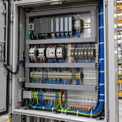
Panel design software combines schematic data with a 2D or 3D enclosure layout: DIN rails, ducts, breakers, busbars and door cut-outs. Good tools calculate wire lengths, generate drilling data and check that components physically fit. For switchboards and control panels, the layout must also satisfy the assembly standard: IEC 61439 for low-voltage switchgear assemblies (see our IEC 61439 guide), UL 508A for industrial control panels in North America, and IEC 60204-1 or NFPA 79 for machinery.
One check that many teams skip is temperature rise. IEC TR 60890 provides a calculation method for verifying temperature rise of assemblies up to defined current limits. A simplified first estimate uses heat balance:
ΔT = P / (k × Ae)
where P is total power loss inside the enclosure in watts, Ae is the effective cooling surface in m², and k is a heat transfer coefficient, roughly 5.5 W/(m²·K) for painted sheet steel in still air.
Worked example. A control panel contains a VFD dissipating 250 W, contactors and breakers totalling 90 W, and a 24 V supply losing 30 W, so P = 370 W. A wall-mounted enclosure 1,200 × 800 × 300 mm has an effective surface (back face against a wall excluded) of about 2.2 m² (front 0.96 + two sides 0.72 + top 0.24 + bottom 0.24). Then ΔT = 370 / (5.5 × 2.2) ≈ 31 K. With 35 °C ambient, internal air reaches about 66 °C, above the 40–45 °C most drives and electronics are rated for without derating. Options are a larger enclosure, filtered fans, a heat exchanger, or moving the drive outside. Better panel design software runs this check automatically from component loss data; the formal method in IEC TR 60890 should be used for verification.
Electrical System Design Software for Power Studies
Electrical system design software in the power engineering sense means analysis programs: they model sources, cables, transformers, motors and protective devices, then calculate how the system behaves. These are distinct from drafting tools and are essential for switchgear and substation work.
- Load flow: bus voltages, transformer loading and losses under normal and contingency conditions.
- Short circuit: fault currents per IEC 60909 or ANSI/IEEE C37 methods, used to verify breaker interrupting and bus withstand ratings. See our fault current calculation guide.
- Protection coordination: time-current curves for relays, fuses and breakers, checked against transformer damage curves (IEEE C57.109) and inrush points.
- Arc flash: incident energy and arc flash boundaries per IEEE 1584, producing labels required by NFPA 70E. Our arc flash study guide explains inputs.
- Motor starting and harmonics: voltage dip on starting, and harmonic distortion against IEEE 519 limits.
When comparing the best electrical design software for studies, look at the quality of the device library, which standards are implemented, how results are reported and whether the model can import or export the one-line drawing. 3D electrical design software and BIM tools increasingly link to these engines, but the calculation itself still needs a validated analysis program and an engineer who understands its assumptions.
How to Choose the Best Electrical CAD Software
There is no single best electrical CAD for every team. Use these criteria to narrow down electrical engineering drawing software and electrical project software:
- Deliverables: list what you issue (single lines, schematics, panel layouts, cable schedules, floor plans, studies). Choose tools that produce them natively.
- Standards: IEC 60617 or IEEE 315 symbols, IEC 81346 designations, IEC 61082 document rules, and the ability to switch between them for export projects.
- Exchange formats: DWG/DXF for drawings, PDF for issue, IFC for BIM, spreadsheet export for schedules, and IEC 61850 SCL files for substation automation.
- Database and reuse: macros or typical circuits for repeated feeders and motor starters save time on switchgear lineups.
- Collaboration: multi-user access, check-in and check-out, and revision history.
- Total cost: licence model, training time and library maintenance, not just the purchase price.
For electrical layout software and electrical blueprint software used in buildings, coordination with architects and the ability to schedule panels automatically matter most; our panel schedule guide shows what those schedules should contain. Run a short pilot: draw one real feeder and one motor starter in each candidate tool and compare the time taken and the quality of the reports.
Next Steps: Specifying and Sourcing Equipment from Your Design
Whatever software you use, the equipment manufacturer needs clear, consistent data. When you send an RFQ for switchgear, transformers or substations, include:
- The single line diagram in PDF and native format, with ratings for every device.
- Equipment schedules: switchgear lineup with feeder ratings, breaker types and protection relays; transformer kVA, voltage ratio, vector group, impedance and cooling.
- Short-circuit study results or at least available fault level and X/R at each bus.
- Control schematics or a functional description for interlocks, transfer schemes and SCADA interfaces.
- Applicable standards: IEC 62271 and IEC 61439, or ANSI/IEEE C37 and UL; IEC 60076 or IEEE C57.12.00 for transformers.
- Site conditions: altitude, ambient, indoor or outdoor, IP or NEMA rating.
MARS manufactures HV and LV switchgear, including KYN28 metal-clad withdrawable switchgear, SF6 ring main units and IEC 61439 low-voltage boards (GGD, GCS and MNS types), plus distribution and power transformers and compact transformer substations. MARS does not sell design software; its engineering team returns general arrangement drawings, single line and schematic submittals for your approval and accepts witness at FAT. Typical lead time for switchgear is 25–45 days. Send your design package through the quote request page.
Frequently asked questions
What is the best software for electrical schematics?
The best software for electrical schematics is a database-driven electrical CAD tool that automates wire numbering, contact cross-references, terminal plans and bills of materials, with IEC 60617 or IEEE 315 symbol libraries. For occasional small diagrams, a general diagramming tool or free open-source electrical CAD may be enough. Choose based on project size, revision volume and the formats your clients require.
Is there free electrical design software?
Yes. Free options include open-source electrical CAD programs with IEC and NEMA symbol libraries, free tiers of commercial tools with sheet or project limits, and browser-based diagram makers. They work well for learning, concept sketches and small control panels. Check export formats and commercial licence terms before using them for paid projects, and verify any downloaded schematics before construction.
Can I create a wiring diagram online?
You can create a wiring diagram online with browser-based diagramming tools that include electrical symbol sets. They are convenient for collaboration and quick sketches. However, most online tools lack automatic wire numbering, cross-referencing and terminal reports, so for production drawings of control panels or switchgear a dedicated electrical CAD program is more reliable and easier to revise.
What software do electrical engineers use for power system studies?
Electrical engineers use power system analysis software for load flow, short-circuit, protection coordination, motor starting, harmonic and arc flash studies. These programs implement standards such as IEC 60909, ANSI/IEEE C37 and IEEE 1584 and contain device libraries for breakers, relays, fuses and transformers. They complement, rather than replace, CAD tools used to draw the single line diagram.
What is the difference between electrical CAD and general CAD?
General CAD draws geometry; a symbol is just a block of lines. Electrical CAD treats each symbol as a device with attributes, contacts and terminals stored in a project database. That allows automatic wire numbering, cross-references, error checks and reports such as BOMs and terminal lists. General CAD remains useful for layouts, site plans and drawings exchanged in DWG or DXF.
Do I need 3D electrical design software?
3D electrical design software is valuable when you build many panels or switchboards, need accurate wire lengths, want clash checks between components and ducts, or must coordinate cable routes with building models. For simple panels or single-line work, 2D electrical CAD is usually sufficient. The 3D benefit depends on having reliable 3D models of the parts you use.
Written and reviewed by the MARS application engineering team in Shanghai, who specify and test transformers, switchgear, substations and battery storage for projects in 40+ countries. Last updated .
Tags: electrical design software electrical schematic design software wiring diagram drawing software free electrical drawing software electrical panel design software