Key takeaways
- Distribution transformers step down medium distribution voltages (typically 11 kV to 33 kV) to utilisation voltages (400 V three-phase / 230 V single-phase or 480 V / 120 V) under standards such as IEC 60076 and IEEE C57.12.00.
- The core operating principle relies on Faraday's law of electromagnetic induction, transferring alternating electrical energy between magnetically coupled circuits without physical contact or frequency change.
- Distribution units feature distinct physical footprints depending on mounting type, including cylindrical pole-mounted cans, compartmentalised green pad-mounted enclosures, and indoor cast-resin enclosures.
- Unlike transmission transformers that operate near full rated capacity continuously, distribution transformers are engineered for lower no-load (core) losses because they run at variable, partial loads averaging 40% to 60% capacity.
- Specifying distribution equipment requires defining primary/secondary voltages, rated power (kVA/MVA), vector group (e.g., Dyn11), percentage impedance (%Z), and environmental enclosure ratings.
Quick answer: In power networks, transformers electricity distribution refers to static electromagnetic assets engineered to step down medium-voltage utility supplies (ranging from 11 kV to 36 kV) to safe, low-voltage consumer levels (such as 400 V / 230 V or 480 V / 240 V). They provide galvanic isolation, voltage stabilisation, and energy delivery to commercial, industrial, and residential installations.
Electrical power generation typically occurs far from consumer centres, requiring high-voltage transmission lines (110 kV to 765 kV) to minimise resistive line losses over long distances. As bulk power nears urban centres and industrial parks, substations lower the voltage to medium-voltage (MV) distribution levels. The final, critical link in this infrastructure is the distribution transformer, which converts medium voltage into low voltage (LV) suitable for machinery, building services, and domestic appliances. Understanding the engineering, construction, and specification of these assets is essential for plant engineers, utility operators, and procurement specialists managing electrical infrastructure.
Transformer Meaning and Scientific Definition
The foundational transformer meaning describes a static electrical machine that transfers electrical energy between two or more circuits through the mechanism of mutual electromagnetic induction. Under the rigorous transformer science definition, it operates without moving parts, converting alternating current (AC) at a given voltage and current into alternating current at a different voltage and current while maintaining an identical operational frequency (50 Hz or 60 Hz).
To formally define electrical transformers in engineering terms, consider the apparatus as two or more electrically isolated, magnetically linked coils wound around a shared ferromagnetic or grain-oriented silicon steel core. When an alternating voltage is applied to the primary winding, it creates a time-varying magnetic flux in the core per Faraday's law of induction:
e = -N (dΦ/dt)
Where e is the induced electromotive force (EMF), N is the number of turns, and dΦ/dt is the rate of change of magnetic flux. This changing flux links with the secondary winding, inducing an alternating voltage proportional to the turns ratio: Vp / Vs = Np / Ns = Is / Ip. Because power remains constant minus internal losses, stepping down the voltage proportionally increases the available current. The precise engineering of these winding ratios and magnetic circuits is detailed further in our guide to transformer internal components and core designs.
What Is the Function of a Transformer in Power Systems?
The primary function of transformer equipment across modern electrical grids is to manage voltage profiles, optimise thermodynamic efficiency, and ensure operational safety. Without voltage conversion, transmitting bulk alternating current over long distances would be economically impossible due to extreme resistive line losses, which follow Joule's heating law: Ploss = I2R.
The fundamental purpose of transformer installations across the grid lifecycle encompasses several operational imperatives:
- Transmission loss reduction: By stepping up generator voltage from 11 kV to transmission thresholds of 132 kV, 275 kV, or 400 kV, current decreases by an inverse ratio. Reducing current by a factor of ten slashes resistive conductor losses by a factor of one hundred. A deeper exploration of these high-voltage grid topologies is available in our transmission transformer engineering guide.
- Voltage level segregation: Transformers segregate extra-high voltage (EHV) bulk transmission, medium-voltage sub-transmission (typically 11 kV to 33 kV), and low-voltage end-use (400 V three-phase / 230 V single-phase).
- Galvanic isolation: The absence of direct electrical connection between primary and secondary windings prevents direct current (DC) propagation, isolates system disturbances, and enhances touch-potential safety on the customer side.
- Fault level and impedance management: The transformer's internal percentage impedance (%Z) acts as a physical barrier that limits prospective short-circuit fault currents downstream, protecting switchgear and switchboards.
What Is a Transformer Used for in Electricity Distribution?
Answering what is a transformer used for specifically within distribution networks focuses on localised power conversion, phase transformation, and voltage regulation for end consumers. Unlike grid-level transmission units that move hundreds of megavolt-amperes (MVA) continuously, distribution units handle ratings between 15 kVA and 3,150 kVA, stepping primary distribution feeds down to utilisation voltages.
In commercial, civil, and industrial systems, transformers electricity distribution hardware provides specific operational roles:
- Stepping down grid feeders: Converting 11 kV, 22 kV, or 33 kV underground or overhead network feeders down to standard 400/230 V (IEC markets) or 480/277 V and 208/120 V (ANSI/IEEE markets).
- System neutral creation: Using secondary star (wye) configurations—most commonly Dyn11 or Dyn1 configurations—distribution transformers provide a stable, grounded neutral point essential for single-phase consumer circuits and earth-fault protection.
- Industrial load matching: Supplying high-current, low-voltage power directly to motor control centres (MCCs), arc furnaces, and commercial building distribution boards.
- Mitigating harmonic pollution: Distribution units can incorporate specialised electrostatic shields or zig-zag winding arrangements to suppress third-order harmonics generated by non-linear electronic and inverter loads. Engineers can consult our sizing framework on how to size a distribution transformer to account for these load profiles.
What Does an Electrical Transformer Look Like in the Field?
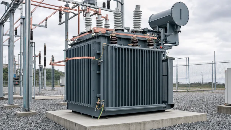
To the question of what does an electrical transformer look like, the physical appearance varies dramatically based on whether the unit is designed for overhead pole mounting, outdoor ground-level pads, or indoor electrical switchrooms. However, all external architectures reflect basic engineering requirements: containment, cooling, electrical clearance, and cable or conductor termination.
Field personnel and inspectors typically encounter three primary physical profiles in distribution networks:
- Pole-mounted transformers: These are compact, cylindrical steel tanks suspended on utility poles. They feature prominent ceramic or polymer high-voltage bushings on top that receive bare overhead conductors, small low-voltage spade terminals on the side, an oil level gauge, and external grounding lugs.
- Pad-mounted compartmentalised transformers: Installed on concrete pads in residential neighbourhoods and commercial parks, these units are enclosed in heavy-gauge, tamper-resistant green or grey sheet-steel cabinets. They feature dual lockable doors that swing open to reveal two separated compartments: a medium-voltage dead-front side with elbow arresters and insulated separable connectors, and a low-voltage side equipped with flat terminal stabs. Learn more about regional enclosures in our review of pad-mounted transformers ANSI vs IEC designs.
- Dry-type indoor transformers: Typically installed inside ventilated metal kiosks or clean plant rooms, dry-type units lack dielectric oil. They feature thick, epoxy-resin-encapsulated coils wound around a bare steel core, mounted on anti-vibration pads, with copper or aluminium busbar stabs protruding for cable connections.
- Substation oil-immersed transformers: Larger units (500 kVA to 3,150 kVA) resemble rectangular corrugated steel tanks with external cooling fins or radiators, an elevated oil conservator tank with a silica gel breather, a top-mounted Buchholz relay, and medium-voltage cable termination boxes.
Technical Comparison: Distribution Transformers vs Transmission Transformers
A functional engineering contrast between distribution units and bulk transmission units highlights fundamental divergences in duty cycle, loss optimisation, impedance, and standardisation. The table below delineates the engineering criteria defined by IEC 60076, IEEE C57.12.00, and regional efficiency directives such as EN 50588-1.
| Engineering Parameter | Distribution Transformer | Transmission Transformer |
|---|---|---|
| Typical Power Rating | 15 kVA to 3,150 kVA | 40 MVA to 1,000 MVA+ |
| Primary Voltage Range | 3.3 kV to 36 kV | 110 kV to 765 kV+ |
| Secondary Voltage Range | 120 V to 690 V (LV utilisation) | 33 kV to 275 kV (sub-transmission) |
| Primary Cooling Medium | ONAN, KNAN (ester), or AN (dry cast resin) | ONAF, OFAF, ODAF, or ODAW |
| Average Loading Profile | Cyclical, intermittent (40% to 60% average load) | Continuous, base-load (80% to 100% load) |
| Loss Optimisation Design | Maximised for minimal no-load (core) loss | Maximised for minimal load (copper I²R) loss |
| Short-Circuit Impedance (%Z) | Typically 4.0% to 6.25% | Typically 10.0% to 18.0%+ |
| Tap Changer Mechanism | Off-Circuit Tap Changer (OCTC: ±2.5%, ±5%) | On-Load Tap Changer (OLTC: 16 to 33 steps) |
| Standard Enclosure / Tank | Corrugated wall, sealed hermetic tank, or pad-mount | Rigid plate tank with detachable radiator banks |
Because distribution units remain energised 24 hours a day while consumer load fluctuates significantly, designing for extremely low iron (no-load) losses is critical for meeting modern efficiency regulations, as outlined in our technical analysis of oil-immersed vs dry-type transformers.
Step-by-Step Distribution Transformer Commissioning Procedure
Energising a new distribution transformer within an electrical network requires an orderly engineering sequence to verify insulation integrity, phase alignment, and safety interlocks prior to load connection. Adhering to the following sequential protocol prevents catastrophic flashovers and equipment damage.
- Visual and mechanical inspection: Inspect the tank, cooling fins, and bushings for transit damage, structural deflection, paint degradation, or fluid leakage. Confirm that the tank grounding boss is bonded to the main substation earth grid using appropriately sized copper tape (e.g., 70 mm² copper conductor).
- Insulation resistance (Megger) verification: Measure insulation resistance between high-voltage to low-voltage windings, high-voltage to ground, and low-voltage to ground using a calibrated 1,000 V or 2,500 V DC insulation tester, ensuring values conform to minimum manufacturer and standard thresholds (typically >1,000 MΩ for HV windings at 20°C).
- Winding resistance and turns ratio test: Perform a low-resistance ohmmeter test across all phases and tap positions to verify internal connection integrity. Conduct a turns ratio (TTR) measurement across all taps to verify that voltage transformation ratios stay within the ±0.5% tolerance prescribed by IEC 60076-1.
- Dielectric breakdown testing of insulating liquid: For oil-immersed units, draw a bottom fluid sample and measure its dielectric breakdown strength in an oil test cell; mineral oil must withstand a minimum of 30 kV across a standard 2.5 mm gap (or >50 kV for newly treated fluid).
- Protection loop and trip circuit verification: Mechanically verify trip and alarm circuits connected to the Buchholz relay, oil temperature indicator (OTI), winding temperature indicator (WTI), and pressure relief device (PRD), confirming proper signaling to the upstream medium-voltage vacuum circuit breaker.
- Phasing check and energisation: Energise the transformer under no-load conditions from the medium-voltage side. Measure phase-to-phase and phase-to-neutral voltages on the low-voltage bushings to verify correct voltage magnitude and phase rotation sequence (e.g., standard phase sequence clockwise) before closing the low-voltage main air circuit breaker to supply customer loads.
Next steps: specifying and sourcing
When preparing technical specifications or requests for quotation (RFQ) for distribution equipment, precise technical data ensures optimal performance and eliminates procurement delays. Project engineering teams must define site operating altitude, ambient temperature extremes, required primary and secondary voltage levels, kVA rating, winding conductor material (copper or aluminium), impedance percentage (%Z), and preferred cooling methodology.
Explore our engineering portfolios for robust oil-immersed distribution transformers, high-safety indoor dry-type cast resin transformers, or utility-grade pad-mounted transformers. To submit bespoke electrical single-line diagrams (SLDs) or tender data sheets for a rapid technical appraisal and commercial bid, connect directly with our engineering department through our transformer quotation request portal.
Frequently asked questions
what is a transformer used for
A transformer is used to step alternating current voltage up or down between different circuits while keeping the frequency unchanged. In power grids, it steps voltage up for efficient, long-distance transmission and steps it down to safe levels for industrial, commercial, and residential use.
what is function of transformer
The function of a transformer is to transfer electrical power between isolated circuits via mutual electromagnetic induction. It converts incoming voltage and current into required operating levels, provides galvanic isolation between systems, and limits short-circuit fault levels through internal impedance.
what does an electrical transformer look like
An electrical transformer generally looks like a heavy steel tank or enclosure fitted with cooling fins or radiators, external porcelain or polymer bushings, and cable termination boxes. Depending on the installation, it may appear as a cylindrical pole-mounted canister, a green metal outdoor cabinet, or a ventilated indoor kiosk.
What is the difference between a step-up and step-down transformer?
A step-up transformer has more secondary winding turns than primary turns, resulting in an output voltage higher than the input voltage. A step-down transformer features fewer turns on the secondary winding, yielding an output voltage lower than the input, which is the standard setup for distribution networks.
Why are transformers used in electricity distribution instead of direct DC lines?
Transformers operate on alternating current because changing magnetic flux is required to induce voltage across windings. AC distribution allows simple, highly reliable passive transformers to adjust voltage levels with over 98% efficiency, which was historically impractical with direct current circuits.
What is the standard lifespan of a distribution transformer?
A standard distribution transformer designed and maintained to IEC or IEEE specifications has an expected operating lifespan of 25 to 35 years. Lifespan is governed by thermal loading and the degradation rate of solid winding insulation paper (Kraft paper) and dielectric oil.
Tags: transformers electricity distribution purpose of transformer what is function of transformer transformer meaning


