Key takeaways
- A transformer nameplate provides legal, thermal, and electrical parameters mandated by standards such as IEC 60076-1 and IEEE C57.12.00.
- Nameplate percentage impedance (%Z) directly determines prospective short-circuit fault levels and dictates cable breaking capacity sizing.
- Pad-mounted units specify configuration schemes like radial or loop feed alongside bushing well arrangements and dead-front switching ratings.
- Vector group notations like Dyn11 describe high-voltage winding geometry, low-voltage configuration, neutral provision, and phase displacement angle.
- Field verification of physical nameplate data against factory routine test certificates is an essential step before energisation.
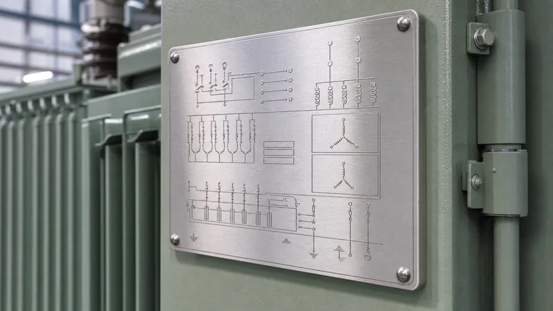
Quick answer: A transformer nameplate is the permanent metal rating plate affixed to the tank that specifies an apparatus's fundamental electrical, thermal, mechanical, and operational limits. Mandated by standards such as IEC 60076-1 (Clause 8) and IEEE C57.12.00, it details ratings including rated power (kVA/MVA), rated voltages, frequency, short-circuit impedance (%Z), vector group, and insulation levels.
Every power distribution network relies on precise equipment parameters to operate safely and effectively. Whether commissioning equipment in the field, sizing circuit breakers, or setting up numerical protection relays, engineers must rely on the equipment rating plate as the definitive legal and technical record of capability. Discrepancies between physical site assumptions and actual rating data risk protective tripping, severe overheating, insulation breakdown, or catastrophic damage during through-fault conditions. Understanding how to interpret the technical data stamped onto both liquid-filled and dry-type units prevents engineering errors during installation and commissioning.
Mandatory Data on a Transformer Nameplate
International standards mandate specific baseline information on every rating plate to ensure safe integration and operation. Under IEC 60076-1 Clause 8.2 and IEEE C57.12.00 Section 5.12, each transformer name plate must be constructed from corrosion-resistant material, such as 304 or 316 stainless steel, and stamped, etched, or engraved so that details remain legible throughout the operational lifecycle.
The standard data requirements differ marginally between European/international frameworks and North American conventions, though both capture core operational thresholds:
| Parameter / Field | IEC 60076-1 Requirement | IEEE C57.12.00 Requirement | Engineering Significance |
|---|---|---|---|
| Manufacturer & Serial Number | Clause 8.2 (a, b) | Section 5.12 (1, 2) | Traceability to factory routine test reports |
| Rated Power (kVA or MVA) | Continuous MVA base | Continuous kVA base | Defines nominal thermal capacity by cooling class |
| Cooling Class Designation | e.g., ONAN, ONAF, OFAF | e.g., ONAN, ONAF, KNAN | Dictates forced/natural air thermal limits |
| Rated Voltages & Taps | HV and LV in V or kV | HV and LV in V or kV | Defines nominal turns ratio and tap range increments |
| Frequency (Hz) | 50 Hz or 60 Hz | 60 Hz (standard US) | Dictates core flux density saturation points |
| Number of Phases | 1 or 3 | 1 or 3 | Identifies system architecture |
| Connection / Vector Group | e.g., Dyn11, YNd11 | Vector diagram & angular shift | Determines phase angle shift and zero-sequence grounding |
| Impedance Voltage (%Z) | Percent at rated current | Percent at reference base | Determines prospective fault current and busbar drop |
| Insulation Level (BIL / AC) | LI / AC levels (kV) | Basic Lightning Impulse (kV) | Surge arrester selection and dielectric margins |
| Temperature Rise Limits | Winding / Top Oil (°C) | Winding / Top Oil (°C) | Insulation life expectancy benchmark (e.g., 65°C rise) |
| Total Weight & Oil Volume | Core, coil, tank, fluid (kg) | Untanking weight, fluid (L/kg) | Rigging, transport, and civil foundation capacity |
Accurate nameplate reading prevents system designers from under-sizing LV switchboards or applying incorrect withstand parameters, which can be reviewed alongside radial feed vs loop feed architectures to ensure line and load balance.
How to Read a Pad Mounted Transformer Nameplate
A pad mounted transformer nameplate contains unique compartment-specific information reflecting its dead-front, tamper-resistant enclosure and underground distribution design. Affixed inside the low-voltage or high-voltage termination compartment, this plate documents both electrical parameters and mechanical layout diagrams.
When inspecting a pad-mounted installation, pay specific attention to the following details:
- Feed Configuration: Indicates whether the unit is radial feed (single set of primary bushings) or loop feed (dual sets of primary bushings designated H1A, H2A, H3A and H1B, H2B, H3B), as explored in our engineering guide to transformer pad engineering and sizing.
- Switching Ratings: If an internal under-oil two-position or four-position load-break switch is fitted, the continuous and load-break current ratings (typically 200 A or 300 A at 15 kV to 35 kV) are explicitly marked.
- Fusing Scheme: Identifies internal protection elements, typically combination Bay-O-Net current-sensing or dual-sensing fuses placed in series with under-oil partial-range current-limiting back-up fuses (ELSP). The plate states the maximum interrupt rating (often 50 kA symmetrical).
- Insulating Fluid Specification: Identifies whether the tank contains mineral oil (Class I / II per IEC 60296) or high-fire-point natural ester fluid (e.g., FR3 meeting ASTM D6871). This rating determines clearance envelopes under NFPA 70 Article 450.
- Core/Coil Material: Copper (Cu) or aluminium (Al) winding composition, which governs physical weight, dynamic fault withstand, and ohmic losses.
For industrial sites needing ground-level distribution solutions, consulting specs for a pad-mounted transformer ensures matching terminal throat geometry and fusing clearances prior to construction.
Decoding a Pole Mounted Transformer Nameplate
A pole mounted transformer nameplate reflects lightweight overhead equipment parameters, typically documenting single-phase distribution units (e.g., 10 kVA to 333 kVA) or three-phase clustered overhead banks. Because pole-top structures carry physical load limitations, the total mass and mounting bolt spacing (per ANSI C57.12.20) are prominently displayed.
Key items to verify on an overhead nameplate include:
- High-Voltage Rating and Dual-Voltage Switches: Single-phase units often list combinations like 7200/12470Y or 14400/24940Y V. When an external series-parallel dual-voltage switch is present, the nameplate provides clear schematic diagrams showing switch positions for both voltage inputs.
- Low-Voltage Connections: Three LV spade terminals (typically X1, X2, X3) permit split-phase three-wire supply (120/240 V) or parallel connection (120 V only). The schematic illustrates internal winding links for cross-connecting coils.
- Lightning Arrester and Tank Grounding: Notes direct provisions for surge arrester mounting brackets and clarifies whether the tank interior ground strap connects internally to the neutral terminal (X2).
- Impedance Tolerances: Overhead units typically demonstrate lower short-circuit impedance, often between 1.5% and 3.0%, to minimise downstream voltage regulation drop over long distribution feeders.
For utilities running medium-voltage rural or suburban overhead feeders, reviewing ratings on a pole-mounted transformer clarifies weight and pole-loading specifications prior to line-crew deployment.
Calculating Fault Current and Cable Sizing from Nameplate Data
Nameplate parameters provide the exact values required to calculate prospective symmetrical short-circuit current at the secondary terminals. Relying on default estimates instead of the actual tested impedance value (%Z) on the plate risks installing switchgear with inadequate short-circuit breaking capacity (Icu).
Consider an oil-immersed distribution transformer with the following nameplate values:
- Rated Capacity ($S_n$): 1500 kVA (1.5 MVA)
- Rated Secondary Line-to-Line Voltage ($V_{LV}$): 400 V (0.4 kV, 3-phase)
- Rated Primary Voltage ($V_{HV}$): 11,000 V (11 kV)
- Short-Circuit Impedance ($%Z$): 5.75% (measured at 75°C reference)
First, calculate full-load rated secondary current ($I_{FLC}$):
$$I_{FLC} = \frac{S_n}{\sqrt{3} \times V_{LV}} = \frac{1,500,000}{\sqrt{3} \times 400} = \frac{1,500,000}{692.82} = 2165.1\text{ A}$$
Assuming an infinite primary busbar source, the prospective symmetrical maximum secondary fault current ($I_{sc}$) is determined using the nameplate %Z:
$$I_{sc} = \frac{I_{FLC}}{\%Z / 100} = \frac{2165.1}{0.0575} = 37,654\text{ A} = 37.65\text{ kA}$$
If the source fault capacity ($S_{source}$) on the 11 kV grid is limited to 250 MVA, the source impedance ($Z_{source}$) in per-unit on a 1.5 MVA base is:
$$Z_{source} = \frac{S_{base}}{S_{source}} = \frac{1.5\text{ MVA}}{250\text{ MVA}} = 0.006\text{ pu}$$
$$Z_{total} = Z_{source} + Z_{transformer} = 0.006 + 0.0575 = 0.0635\text{ pu}$$
$$I_{sc(actual)} = \frac{2165.1}{0.0635} = 34,096\text{ A} = 34.10\text{ kA}$$
This calculation proves that the secondary main circuit breaker must possess an ultimate breaking capacity rating of at least 36 kA or 50 kA. Engineers running pre-commissioning checks can cross-reference these principles in our guide on how to test a transformer.
Vector Groups and Connection Diagrams Explained
The vector group notation on a transformer nameplate defines the winding topology and the angular phase displacement between the primary and secondary voltage vectors. Expressed using alphanumeric codes governed by IEC 60076-1 Clause 6, this nomenclature dictates whether transformers can safely operate in parallel.
The notation uses standardised conventions:
- Uppercase letters: High-voltage winding connection (D = Delta, Y = Star/Wye, Z = Zigzag).
- Lowercase letters: Low-voltage winding connection (d = delta, y = star/wye, z = zigzag).
- Letter 'N' or 'n': Indicates that the neutral point is brought out to an external terminal for earthing or neutral conductor connection.
- Clock hour figure (0 to 11): Represents the phase displacement angle of the secondary phase voltage relative to the primary phase voltage, with each hour corresponding to 30 degrees of lagging displacement.
For example, a unit marked Dyn11 indicates a delta-connected HV winding (D), a star-connected LV winding (y) with accessible neutral (n), and an LV vector lagging the HV vector by 330 degrees (or leading by 30 degrees, represented by 11 o'clock). Paralleling a Dyn11 transformer with a Dyn5 transformer causes a 180-degree phase discrepancy, producing severe short-circuit circulating currents that will trip primary circuit breakers and potentially destroy winding assemblies.
Factory Acceptance and On-Site Nameplate Verification Checklist
Engineers must rigorously check the rating plate upon delivery to site prior to foundation setting, as documented in our guide to transformer thermal limits and winding temperature. Discrepancies between approved design submittals and factory stamped plates can invalidate warranties and endanger site safety.
Execute this verification sequence during site acceptance:
- Physical Plate Condition: Ensure the plate is 316 stainless steel, securely fastened with stainless steel rivets, devoid of chemical damage, and readable through protective cabinet viewing windows.
- Voltage Ratio and Tap Changer Table: Compare the stamped primary voltage steps (e.g., 11,000 V nominal with ±2 × 2.5% taps: 11,550 V, 11,275 V, 11,000 V, 10,725 V, 10,450 V) with the physical mechanical indicator on the off-circuit tap changer (OCTC) switch handle.
- Tested vs Nominal Impedance: Check that the stamped factory-tested %Z falls within the tolerance limits allowed by IEC 60076-1 Table 1 (typically ±10% of declared value for impedance ≥ 10%, or ±7.5% for two-winding units < 10%).
- Dielectric and Thermal Ratings: Confirm the insulation class matches environmental requirements (e.g., 65°C average winding rise over 30°C ambient for oil units, or 100°C/150°C rise for Class H dry-type units).
- Fluid Details and Weights: Verify that the fluid type, mass of active parts (core and windings), total transport weight, and untanking mass match crane rigging and slab structural calculations.
Validating these items against the routine test certificate eliminates commissioning delays and guarantees compliance with local electrical safety regulations.
Next steps: specifying and sourcing
When specifying distribution and power transformers for infrastructure, industrial plants, or commercial developments, precise nameplate documentation forms the baseline for factory testing and commissioning. Prepare your single-line diagrams, required vector groups, nominal system voltages, tap ranges, BIL ratings, and short-circuit impedance requirements before placing an order. Explore our complete selection of fluid-filled equipment on the oil-immersed transformer page, or contact our application engineering team via the request a quotation page to receive customised specification sheets, dimension drawings, and factory test templates for your project.
Frequently asked questions
What is the most critical information on a transformer nameplate?
The most critical items are rated power (kVA/MVA), primary and secondary voltages, short-circuit impedance (%Z), and the vector group. These parameters govern current-carrying capability, downstream fault levels, and whether the unit can safely parallel with existing equipment.
Why does a transformer nameplate show two or three kVA ratings?
Multiple kVA ratings correspond to different operational cooling stages. For instance, a plate marked ONAN/ONAF 1000/1333 kVA indicates the transformer operates safely at 1000 kVA under natural convection cooling, and at 1333 kVA when external cooling fans are running.
Can you parallel transformers with different nameplate impedance values?
Yes, but they will not share the total load proportionally to their kVA ratings. The transformer with the lower percentage impedance will carry a disproportionately higher share of the load, risking severe overheating even if total load is within combined ratings.
What does BIL mean on a transformer name plate?
BIL stands for Basic Lightning Impulse Insulation Level, measured in crest kilovolts (kV). It specifies the magnitude of transient lightning and switching surges the winding insulation system can withstand without experiencing dielectric breakdown.
How do you identify a pad mounted transformer nameplate from an overhead unit?
A pad-mounted nameplate specifies dead-front compartmental layout, loop or radial feed switching configurations, and under-oil fuse part numbers. Overhead pole-mounted nameplates focus on single-phase connections, dual-voltage switches, and pole-mounting bracket positions.
Tags: transformer nameplate pad mounted transformer nameplate pole mounted transformer nameplate transformer name plate


