Key takeaways
- Renewable energy integration requires step-up transformers engineered to withstand cyclic thermal loading, DC bias, and severe inverter-generated harmonics per IEC 60076-16.
- Non-linear loads from solar and wind inverters generate harmonic currents that elevate eddy-current losses in windings, requiring calculated K-factor or harmonic factor de-rating.
- Electrostatic shielding placed between primary and secondary transformer windings attenuates high-frequency common-mode voltage transients generated by power conversion systems.
- Bi-directional energy integration alters distribution feeder voltage profiles, necessitating coordinated on-load tap changers and fast-acting reactive power injection.
- Specifying medium-voltage plant transformers for renewable integration demands strict compliance with IEEE 1547-2018 for anti-islanding and fault ride-through capabilities.
Quick answer: Renewable energy integration is the technical process of connecting intermittent, inverter-based renewable generation—such as solar photovoltaics, wind energy, and battery storage—into an electrical grid while maintaining statutory standards for frequency, voltage stability, power quality, and equipment thermal limits.
The engineering requirements of modern utility-scale networks have shifted dramatically from traditional centralised synchronous generation toward distributed inverter-based resources (IBRs). Successfully executing renewable energy integration requires plant designers and substation engineers to resolve unique operational stresses that standard distribution systems were never built to handle. These include bi-directional active and reactive power flows, rapid ramping events, high harmonic content, reduced system physical inertia, and DC bias injected by power electronic converters.
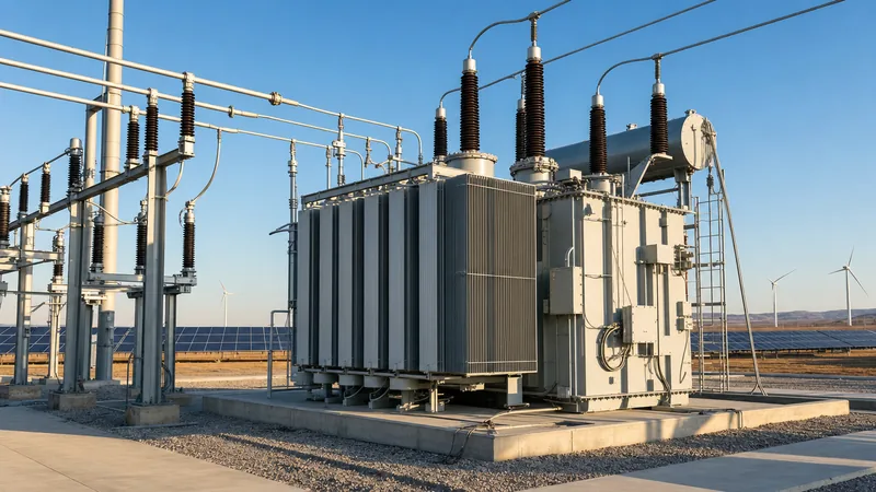
Central to this transition is the interface between the generation facility and the wider utility network: the step-up transformer and its associated switchgear. A standard commercial distribution unit applied to a photovoltaic farm or battery storage yard faces early insulation degradation and thermal failure if not engineered for the harsh harmonic profiles and cyclic loading cycles typical of renewable sites. Sizing and specifying this balance-of-plant equipment correctly requires an exhaustive understanding of international grid codes, loss evaluation methodologies, and mechanical design safeguards.
Core Challenges in Renewable Energy Integration
The technical difficulties of renewable energy integration stem from the intermittent nature of renewable sources and the operational characteristics of solid-state inverters.
Unlike thermal or hydroelectric power stations, which utilise heavy synchronous rotors that provide physical rotational inertia, solar panels and modern wind turbines interface through power electronic converters. This fundamental shift presents four major engineering hurdles:
- Loss of System Inertia: High penetration of non-synchronous generation reduces the rate of change of frequency (RoCoF) ride-through capability, making the grid vulnerable to trip events during transmission line faults.
- Bi-directional Power Flow: Traditional radial distribution feeders operate under the assumption that power flows exclusively downstream from the substation to end users. Active power injection from distributed energy resources elevates line voltages at the receiving end, often exceeding statutory tolerances defined in standards such as EN 50160.
- Power Quality and Harmonics: Inverters operating with high-frequency pulse-width modulation (PWM) inject non-fundamental harmonic currents into the medium-voltage (MV) network. High total harmonic distortion (THD) causes severe resonance, capacitor bank overheating, and parasitic eddy losses in magnetic cores.
- Voltage Fluctuation and Flicker: Fast cloud transients over photovoltaic plants can drop active power output by 60% within seconds. This rapid fluctuation causes voltage sags that standard mechanically switched tap changers cannot mitigate without excessive mechanical wear.
For a detailed systemic breakdown of transmission connection requirements, consult our guide to grid integration of renewable energy sources.
Transformer Engineering for Renewable Integration Systems
Transformers deployed for renewable integration must withstand high harmonic burdens, rapid thermal cycling, and DC current offsets that conventional distribution units do not encounter.
Under IEC 60076-16 (Transformers for wind turbine applications) and IEEE C57.159 (Guide for Application, Design, and Sizing of Power Transformers in Photovoltaic Solar Power Systems), several critical design enhancements are mandatory to prevent premature asset failure.
Foremost among these is managing winding eddy-current losses. In a standard liquid-filled unit, eddy losses account for roughly 5% to 10% of total load losses at 50 Hz or 60 Hz. However, under non-sinusoidal currents rich in 5th, 7th, 11th, and 13th harmonics, winding eddy losses escalate quadratically with harmonic order:
To combat this localized hot-spot overheating, manufacturers must utilise subdivided or continuously transposed conductors (CTC) to suppress eddy currents within copper strands. Furthermore, an earthed electrostatic shield—consisting of a non-closed copper foil placed between the low-voltage (LV) and high-voltage (HV) windings—must be specified. This shield diverts high-frequency capacitive switching surges to earth, protecting the high-voltage distribution insulation system from PWM inverter voltage reflection.
Specifying high-quality dielectric fluid and thermal insulation, such as thermally upgraded kraft paper or Nomex-based hybrid systems, prevents accelerated polymer chain degradation caused by the dynamic loading profiles of solar and wind generation.
Worked Calculation: Harmonic De-Rating and Sizing for a Solar PV Transformer
Accurately sizing a transformer for solar energy integration requires calculating the harmonic loss factor to verify that hot-spot temperatures do not breach thermal class limits under peak generation.
Consider an engineering scenario specifying a three-phase, liquid-immersed step-up transformer connected to a central inverter station. The inverter produces a rated active power of 3,125 kVA at 690 V, operating at a power factor of 0.95 leading/lagging.
Step 1: Input Data and Harmonic Spectrum
- Rated output: $S_n = 3,125\text{ kVA}$
- Secondary line-to-line voltage: $V_2 = 690\text{ V}$
- Fundamental full-load current: $I_1 = \frac{3125}{\sqrt{3} \times 0.690} = 2,615.1\text{ A}$
- Measured or guaranteed harmonic spectrum at inverter terminals:
- Fundamental (h = 1): 100% ($I_1 = 1.0\text{ pu}$)
- 5th Harmonic (h = 5): 4.0% ($I_5 = 0.04\text{ pu}$)
- 7th Harmonic (h = 7): 3.0% ($I_7 = 0.03\text{ pu}$)
- 11th Harmonic (h = 11): 1.5% ($I_{11} = 0.015\text{ pu}$)
- 13th Harmonic (h = 13): 1.0% ($I_{13} = 0.010\text{ pu}$)
- Factory baseline losses at fundamental current: Ohmic loss $P_{I^2R} = 22.0\text{ kW}$; Winding eddy loss $P_{EC-R} = 2.4\text{ kW}$; Other stray loss $P_{OSL-R} = 1.2\text{ kW}$.
Step 2: Calculate the Harmonic Loss Factor for Winding Eddy Currents ($F_{HL}$)
Per IEEE C57.110 clause 5.3, the harmonic loss factor for winding eddy currents is determined by:
$$F_{HL} = \frac{\sum_{h=1}^{h_{max}} I_h^2 \, h^2}{\sum_{h=1}^{h_{max}} I_h^2}$$
Calculating the numerator terms:
$$h=1: (1.0)^2 \times 1^2 = 1.000$$
$$h=5: (0.04)^2 \times 5^2 = 0.0016 \times 25 = 0.040$$
$$h=7: (0.03)^2 \times 7^2 = 0.0009 \times 49 = 0.0441$$
$$h=11: (0.015)^2 \times 11^2 = 0.000225 \times 121 = 0.0272$$
$$h=13: (0.010)^2 \times 13^2 = 0.0001 \times 169 = 0.0169$$
Numerator sum = $1.000 + 0.040 + 0.0441 + 0.0272 + 0.0169 = 1.1282$
Denominator sum = $1.0^2 + 0.04^2 + 0.03^2 + 0.015^2 + 0.01^2 = 1.000 + 0.0016 + 0.0009 + 0.000225 + 0.0001 = 1.0028$
$$F_{HL} = \frac{1.1282}{1.0028} = 1.125$$
Step 3: Calculate Adjusted Total Load Loss
$$P_{LL} = P_{I^2R} + (F_{HL} \times P_{EC-R}) + (F_{HL-other} \times P_{OSL-R})$$
Assuming stray loss factor $F_{HL-other} \approx 1.05$:
$$P_{LL} = 22.0 + (1.125 \times 2.4) + (1.05 \times 1.2) = 22.0 + 2.70 + 1.26 = 25.96\text{ kW}$$
This represents an 11.8% increase in load losses directly attributed to inverter harmonics. Consequently, the project engineer must specify a transformer designed for a minimum K-factor of 4 (K-4), or increase the thermal capacity to 3,500 kVA to prevent winding hot-spots from breaching the 65 K average winding temperature rise limit specified in IEEE C57.12.00 Table 5.
Technical Comparison: Equipment Specifications for Integration of Renewable Energy Sources
Equipment selected for the integration of renewable energy sources must match the specific operational profile of the generation asset, whether solar photovoltaic, wind turbine, or battery storage.
The engineering differences between standard grid distribution transformers and units customised for renewable integration are outlined in the specification matrix below:
| Engineering Parameter | Standard Utility Transformer | Solar PV Step-Up Unit | Wind Turbine Step-Up Unit | BESS Bidirectional Unit |
|---|---|---|---|---|
| Applicable Standards | IEC 60076-1, IEEE C57.12.00 | IEC 60076-16, IEEE C57.159 | IEC 60076-16, IEEE C57.12.00 | IEC 60076-1, IEEE C57.12.00 |
| Harmonic Spectrum Capability | THD < 2%, K-factor = 1 | THD 3-5%, K-4 to K-9 rating | THD 2-4%, K-4 rating | THD 3-6%, K-4 to K-13 rating |
| Electrostatic Shielding | Rarely installed | Mandatory between LV and HV | Mandatory or double-shielded | Mandatory between LV and HV |
| Loading Profile | Continuous baseload | Diurnal cycle (100% midday, 0% night) | Stochastic, fluctuating with wind | Frequent reversal (charge/discharge) |
| DC Influx Tolerance | Negligible (<0.1% rated current) | Up to 0.5% rated current (inverter bias) | Negligible (converter filtered) | Up to 0.5% rated current |
| Thermal Insulation Class | Class A (105 °C) | Class A or Class F hybrid (155 °C) | Class F or H (dry) / High-temp fluid | Class F (dry) or Class A fluid |
| Cooling Arrangement | ONAN | ONAN or ONAF | ONAN / KFAF / AN depending on tower | ONAN / ONAF |
For dedicated wind generation requirements, review our detailed guide on wind turbine transformer engineering and sizing. For systems integrating battery conversion hardware, examine our technical analysis of power conversion systems.
Voltage Regulation and Reactive Power Control Methods
Voltage regulation strategies during renewable energy integration require coordinating dynamic inverter capabilities with physical substation tap changers.
As intermittent renewable generation fluctuates, feeder voltage profiles swing unpredictably. Utilities manage this through three synchronised mechanisms:
- Automated Tap-Changing: Substation power transformers require an On-Load Tap Changer (OLTC) featuring an electronic voltage regulating relay with bi-directional sensing. When local generation pushes voltage higher at the remote bus, the OLTC shifts tap positions to suppress feeder overvoltage.
- Inverter Volt-VAR and Volt-Watt Modes: In accordance with IEEE 1547-2018 Clause 5, modern inverters must continuously modulate reactive power without disconnecting from the grid. By sinking reactive power (operating at an inductive power factor) during high generation periods, the plant directly counteracts voltage rise across transformer and line reactances.
- Dynamic Static Var Compensators (STATCOMs): In large transmission-level renewable parks, external MV STATCOM units or shunt reactors are installed on the substation tertiary winding to provide sub-cycle voltage correction that mechanical switches cannot deliver.
Coordinating these systems ensures that physical transformer tap mechanisms are not subjected to tens of thousands of unnecessary operations annually, which would otherwise lead to mechanical failure and contact burn-out.
Grid Code Compliance and Relay Protection Schemes
Protection engineering for renewable energy integration must account for low short-circuit current contributions from inverter systems during fault conditions.
Conventional utility protection relies on high fault currents to trip magnetic overcurrent elements (ANSI 50/51). However, grid-tied inverters are electronically current-limited to approximately 1.1 to 1.4 times rated current ($I_{rated}$). Consequently, standard overcurrent protection on the MV collector feeder will not operate rapidly during asymmetrical ground faults.
Engineers must implement modern differential and impedance-based schemes:
- Percentage Restrained Differential Protection (ANSI 87T): Serves as the primary protection for the step-up transformer, tuned with harmonic restraint (second harmonic for inrush, fifth harmonic for overexcitation) to prevent nuisance tripping during energisation.
- Directional Phase and Ground Overcurrent (ANSI 67/67N): Required on collector buses to distinguish between internal collector network faults and faults originating upstream in the transmission grid.
- Rate of Change of Frequency (ANSI 81R) and Vector Shift: Provides reliable anti-islanding detection when the local renewable plant becomes decoupled from the bulk power system, compliant with IEEE 1547 requirements.
- Transformer Neutral Grounding: Grounding transformers (zigzag or grounded wye-delta) must be installed on delta collector networks to ensure a stable zero-sequence source for directional ground relays during single line-to-earth faults.
Next steps: specifying and sourcing
Executing a reliable renewable energy integration project requires specifying medium-voltage equipment engineered precisely around your plant's generation profile and local utility grid codes. When preparing your inquiry, provide your single-line diagram, expected inverter harmonic spectrum up to the 25th harmonic, target ambient temperature, and site seismic ratings. Our engineering department reviews these parameters to custom-build high-efficiency step-up equipment. Explore our complete selection of liquid-filled power transformers, heavy-duty pad-mounted transformers, and fully containerised transformer substations. For project-specific evaluations, submit your design files via our transformer quotation page or reach out directly to our engineering team through our contact page.
Frequently asked questions
What is renewable energy integration?
Renewable energy integration is the engineering process of connecting variable, inverter-based electricity generation into an existing power grid safely and reliably. It encompasses electrical infrastructure sizing, harmonic filtering, voltage stability management, and relay protection coordination to ensure uninterrupted transmission.
How do harmonics affect transformers in renewable integration?
Inverter-generated harmonics dramatically increase eddy-current and stray losses within transformer windings and structural core steel. This parasitic heating elevates the winding hot-spot temperature, accelerates dielectric degradation, and requires engineers to specify K-factor rated or harmonic-derated transformers to prevent catastrophic insulation failure.
Why is an electrostatic shield needed in renewable energy transformers?
An electrostatic shield is a grounded, non-closed metallic barrier placed between transformer primary and secondary windings. It decouples high-frequency common-mode voltage spikes generated by inverter PWM switching, preventing high-voltage capacitive transients from propagating into grid-side switchgear.
What is the standard vector group for renewable integration step-up transformers?
The predominant vector group for solar and wind step-up transformers is Dyn11 or YNd11. The delta winding traps third-order zero-sequence harmonics, while the solidly earthed wye configuration provides a stable reference ground for utility protection relays.
How does bi-directional power flow impact grid protection?
Bi-directional power flow disrupts conventional radial overcurrent protection because fault current can flow in either direction. Protection schemes must incorporate directional overcurrent relays, differential elements, and dedicated anti-islanding schemes to isolate faulted feeders properly.
What is the difference between K-factor and factor HL in transformer sizing?
K-factor is an ANSI/IEEE metric indicating a transformer's ability to withstand harmonic currents without exceeding rated temperature rise. Factor HL is the IEC equivalent harmonic loss factor that mathematically quantifies winding eddy-current loss multipliers under non-sinusoidal currents.
Tags: renewable energy integration renewable integration energy integration integration of renewable energy sources grid interconnection


