Key takeaways
- A power line transformer steps down medium-voltage utility distribution power (11 kV to 34.5 kV) to end-user service levels (120 V to 480 V).
- Overhead single-phase units serve low-density residential loads from 10 kVA to 167 kVA, whereas three-phase pad-mounted units support commercial loads up to 5,000 kVA.
- Typical basic impulse insulation levels (BIL) range between 60 kV and 150 kV to withstand atmospheric lightning and switching surges on exposed conductors.
- Operating impedance values (%Z) generally span 1.8% to 5.75%, determining short-circuit fault levels and voltage drop under peak loading.
- Routine field commissioning mandates turns ratio testing, winding resistance verification, insulation resistance screening, and dielectric breakdown checks of insulating fluid.
Quick answer: A power line transformer is an electrical distribution device mounted on utility poles or ground-level pads to step down medium-voltage distribution circuits (typically 11 kV to 34.5 kV) to low-voltage utilisation levels (such as 120/240 V split-phase or 400/480 V three-phase) for direct commercial, industrial, and residential consumption.
Electrical power transmission networks transport energy across vast distances at ultra-high and high voltages to minimize I²R resistive line losses. Once electricity arrives at urban and rural margins, local distribution networks require robust voltage step-down equipment to safely supply end-use infrastructure. While large substation infrastructure acts as the primary gateway from bulk transmission networks, the ubiquitous powerline transformer represents the final link in the grid conversion chain. For a broader overview of upstream bulk power transfer, review our transmission transformer engineering guide. Understanding the operational architecture, thermal performance, and mechanical specification of these line devices is essential for utility engineers, procurement teams, and balance-of-plant electrical contractors tasked with building reliable distribution networks.
What Is a Power Line Transformer and How Does It Operate?
A power line transformer is a static magnetic device that transfers alternating current electrical energy between circuits at identical frequency through mutual electromagnetic induction. According to Faraday’s law of induction, alternating current traversing the high-voltage primary winding creates an alternating magnetic flux within a laminated electrical steel core. This fluctuating flux links with the secondary winding, inducing an electromotive force proportional to the winding turns ratio (Np / Ns = Vp / Vs).
Installed directly within utility distribution corridors, these units interface between medium-voltage distribution feeders and customer service drops. Distribution circuits encounter severe load fluctuations, elevated ambient temperatures, and direct atmospheric overvoltages. As explored in our review of transformers in electricity distribution, a reliable line transformer utilizes thermally upgraded insulating paper immersed in mineral oil or synthetic ester fluid. This insulating liquid performs dual duties: providing dielectric insulation between energized conductors and transferring heat from core and coil assemblies to the ribbed tank surfaces through natural convection (cooling class ONAN). High-permeability grain-oriented silicon steel cores ensure that continuous no-load core losses remain minimal throughout decades of continuous energisation.
Overhead vs Underground Powerline Transformer Configurations
Overhead and underground powerline transformer designs are engineered to accommodate distinct physical environments, grid topologies, and aesthetic regulations. The choice between pole-mounted overhead units and surface-mounted underground units dictates physical footprint, capital expenditure, and asset lifespan.
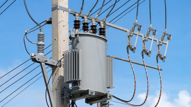
- Overhead Pole-Mounted Units: Suspended directly from wood, concrete, or steel utility poles using heavy-duty mounting brackets, these units are ubiquitous in rural, suburban, and overhead urban grids. Capacities typically range from 10 kVA to 500 kVA. Overhead designs feature high-voltage porcelain or polymer roof bushings connected directly to bare line conductors via expulsion cutouts and surge arresters. For detailed pole hardware specs, consult our power pole transformer engineering guide and examine our complete range of pole-mounted transformers.
- Underground Pad-Mounted Units: Installed at ground level on concrete pads, these transformers serve underground residential distribution (URD) and commercial networks. They feature tamper-resistant, lockable steel enclosures divided into distinct high-voltage and low-voltage cable compartments. Utilizing dead-front shielded elbow connectors rated to IEEE 386, pad-mount designs protect the general public from shock hazards in parks, commercial centers, and planned housing developments. Compare international standards for these enclosures in our guide to pad-mounted transformers ANSI vs IEC, or browse our heavy-duty pad-mounted transformers.
Technical Specifications and Standard Ratings
Standard ratings for a power line transformer are defined by international standards bodies such as IEC (specifically IEC 60076) and IEEE (IEEE C57.12.00, C57.12.20, and C57.12.34). Selecting the proper unit demands careful reconciliation of apparent power (kVA), primary winding insulation levels, tap changer arrangements, and impedance values.
| Parameter | Single-Phase Pole-Mount | Three-Phase Pole-Mount | Three-Phase Pad-Mount |
|---|---|---|---|
| Power Rating Range | 10 kVA – 167 kVA | 30 kVA – 500 kVA | 75 kVA – 5,000 kVA |
| Primary Voltage Range | 2.4 kV – 34.5 kV | 4.16 kV – 34.5 kV | 4.16 kV – 40.5 kV |
| Secondary Voltage Range | 120/240 V (Split-Phase) | 208Y/120 V, 480Y/277 V | 208Y/120 V, 400 V, 480Y/277 V |
| Basic Impulse Level (BIL) | 60 kV – 150 kV | 60 kV – 150 kV | 60 kV – 200 kV |
| Percent Impedance (%Z) | 1.5% – 3.0% | 2.0% – 4.5% | 3.5% – 5.75% |
| Insulating Fluid Options | Mineral Oil, FR3 Ester | Mineral Oil, Synthetic Ester | Mineral Oil, High-Firepoint Ester |
| Standard Enclosure / Cooling | Mild Steel / ONAN | Mild Steel / ONAN | Corrosion-Resistant Steel / ONAN (KNAN) |
Basic impulse insulation levels (BIL) represent the unit's withstand capability against lightning transients. For example, a 15 kV nominal primary system typically specifies a 95 kV BIL, while a 34.5 kV line mandates 150 kV BIL. Percent impedance (%Z) directly governs available short-circuit currents on secondary busbars: lower %Z reduces voltage drop during dynamic motor starting but elevates prospective fault energy levels, requiring higher downstream interrupt ratings.
Loss Evaluation and Sizing Calculations for Line Transformers
Optimising powerline transformer selection requires calculating both operational efficiency and prospective thermal loading over an expected asset lifetime of 30 to 40 years. Total transformer losses comprise fixed no-load core losses (hysteresis and eddy currents in the steel core) and variable load losses (I²R copper losses and stray losses in structural components).
Total cost of ownership (TCO) evaluation formulas permit utility specifiers to penalize inefficient designs during competitive bidding:
TCO = Initial Purchase Price + (A × No-Load Loss in kW) + (B × Full-Load Loss in kW)
Here, factor A typically ranges from €4,000 to €8,000 per kW to reflect continuously capitalized energy wasted 8,760 hours per year, whereas factor B ranges from €1,000 to €3,000 per kW based on anticipated load factors. Sizing calculations for a three-phase line transformer follow the continuous apparent power demand formula:
S (kVA) = (VL-L × IL × √3) / 1000
For instance, an industrial workshop drawing a peak design current (IL) of 550 A at a line-to-line voltage (VL-L) of 480 V demands:
S = (480 V × 550 A × 1.732) / 1000 = 457.2 kVA
Applying a 20% growth margin results in 548 kVA, steering the engineering specification directly to a standardized 630 kVA or 750 kVA liquid-filled pad-mounted unit or medium-voltage power transformer.
Protective Schemes, Earthing, and Grid Safety
A distribution power line transformer operates directly exposed to transient grid surges, line faults, and structural overcurrents, requiring coordinated electrical protection and grounding systems. Primary overvoltage protection depends on metal-oxide varistor (MOV) surge arresters mounted directly adjacent to the high-voltage bushings to divert atmospheric lightning transients to earth before reaching winding paper.
Overcurrent mitigation on overhead units combines an external drop-out expulsion cutout fuse with internal weak-link or bayonet fuses. The drop-out fuse isolates failed transformers from the primary feeder, providing visible air gap disconnection for line maintenance crews. On pad-mounted units, dual-sensing current-limiting fuses or under-oil partial-range back-up fuses clear high-energy faults quietly within sealed tanks. Solid multi-point earthing connects the tank ground lug, low-voltage neutral bushing (X0), and surge arrester grounds to a low-resistance earth electrode grid (typically target impedance < 5 Ω), preventing dangerous touch and step potentials around the public perimeter.
Installation and Field Commissioning Procedure
Commissioning a powerline transformer requires rigorous testing to confirm insulation integrity and winding parameters before grid energisation. Technicians must strictly follow safety lockout/tagout procedures and execute the following numbered testing sequence:
- Receiving Inspection and Physical Verification: Examine external tank finish for transport abrasion, verify pressure-vacuum gauge levels, check fluid sight glass indicators, and inspect ceramic or composite bushings for microfractures.
- Insulation Resistance (Megger) Testing: Apply a DC test voltage (typically 2,500 V or 5,000 V for primary windings; 1,000 V for secondary windings) between HV-to-LV, HV-to-Earth, and LV-to-Earth for 60 seconds to ensure insulation resistance values exceed 1,000 MΩ at 20 °C.
- Turns Ratio and Vector Verification: Measure the transformer turns ratio (TTR) across all de-energised tap changer positions to verify phase alignment, polarity, and tap tolerances within ±0.5% of nameplate values per IEC 60076-1.
- Winding Resistance Measurement: Employ a low-resistance digital ohmmeter to measure DC winding resistances on all phases, confirming that balance between phases does not diverge by more than 2% to detect loose internal clamp connections.
- Dielectric Fluid Breakdown Testing: Extract an oil sample from the bottom drain valve and verify dielectric breakdown strength across a calibrated 2.5 mm electrode gap in accordance with ASTM D877 or IEC 60156 (minimum withstand threshold > 30 kV for new oil).
- System Earthing and Final Energisation: Secure structural grounding connections, confirm phase sequence match with utility feeder buses, close secondary main breakers to verify open-circuit secondary voltage, and record stable energisation parameters.
Next steps: specifying and sourcing
When submitting technical inquiries for medium-voltage line equipment, provide precise operational parameters to receive an accurate factory quotation. Essential data includes nominal primary and secondary voltages, BIL ratings, continuous kVA capacity, impedance tolerances, tap configurations (e.g., ±2 × 2.5% de-energised), and site ambient conditions. Explore our comprehensive portfolios of high-efficiency pole-mounted transformers and heavy-duty pad-mounted transformers engineered to IEEE and IEC standards. For detailed technical evaluations, custom project drawings, and competitive manufacturing tenders, submit your requirements via our transformer quotation page or consult our factory application engineering team directly.
Frequently asked questions
What is the primary function of a power line transformer?
A power line transformer steps down medium-voltage electricity from utility distribution power lines to low utilisation voltages suitable for residential, commercial, or light industrial electrical systems. It also provides galvanic isolation between distribution feeders and consumer premises.
Why do powerline transformers hum during operation?
Powerline transformers hum due to magnetostriction, a physical phenomenon where magnetic flux forces the electrical steel core laminations to microscopic expansion and contraction at twice the operating line frequency. This structural vibration transmits through the insulating oil and tank walls, generating audible sound.
What causes a power line transformer to explode?
Catastrophic failures typically occur when internal electrical arcing vaporizes dielectric insulating oil into explosive hydrocarbon gases faster than the tank pressure relief device can exhaust them. Common triggers include severe lightning impulses exceeding insulation ratings, sustained low-impedance external short circuits, or moisture degradation of internal winding paper.
How long does a utility power line transformer typically last?
The operational lifespan of a utility power line transformer ranges from 30 to 45 years under normal operating conditions. Regular oil testing, conservative loading practices, and effective lightning surge protection can extend operating life well past 40 years.
What is the difference between single-phase and three-phase line transformers?
Single-phase line transformers feature one primary winding phase and provide split-phase 120/240 V outputs for typical residential applications. Three-phase line transformers feature three sets of phase windings to supply balanced 208Y/120 V, 400 V, or 480Y/277 V power for commercial, institutional, and industrial three-phase equipment.
Can a power line transformer be installed indoors?
Standard oil-filled power line transformers are generally prohibited inside occupied commercial buildings unless placed in dedicated, fire-rated transformer vaults equipped with liquid containment sills and automated fire suppression systems. Indoor applications usually employ cast resin or dry-type transformers to eliminate liquid flammability risks.
Tags: power line transformer powerline transformer distribution transformers pole-mounted transformer pad-mounted transformer


