Key takeaways
- Low voltage products operate at or below 1,000 V AC (1,500 V DC) under IEC 60947 and IEC 61439 standards.
- A typical low voltage distribution system couples an incoming transformer tail directly to a main Air Circuit Breaker rated up to 6,300 A.
- Internal separation forms (Form 1 to Form 4b per IEC 61439-2) dictate how functional low voltage devices are isolated from horizontal and vertical busbars.
- Short-circuit prospective fault levels at the LV terminal of a 1,600 kVA transformer routinely exceed 38 kA, requiring busbar cross-sections certified for both thermal and dynamic peak stress.
- Proper discrimination between upstream and downstream low voltage devices prevents nuisance trips and protects critical assets across commercial and industrial infrastructure.
Quick answer: In commercial and industrial power distribution, low voltage products comprise the complete family of electrical apparatus rated up to 1,000 V AC or 1,500 V DC designed to isolate, switch, measure, and protect electrical circuits. Within prefabricated substations and industrial facilities, these components form the critical bridge between step-down transformers and end-user load centres.
Substation engineers and EPC contractors face strict performance criteria when integrating low voltage equipment. Specifying the correct switchgear lineup requires balancing prospective fault currents, thermal rise, internal separation forms, and operational safety. In modern secondary substations—such as those detailed in our unit substation engineering guide—the low-voltage compartment must reliably handle downstream switching surges, fault clearing, and power monitoring under high ambient operating temperatures.
Core Low Voltage Products in Modern Substation Architecture
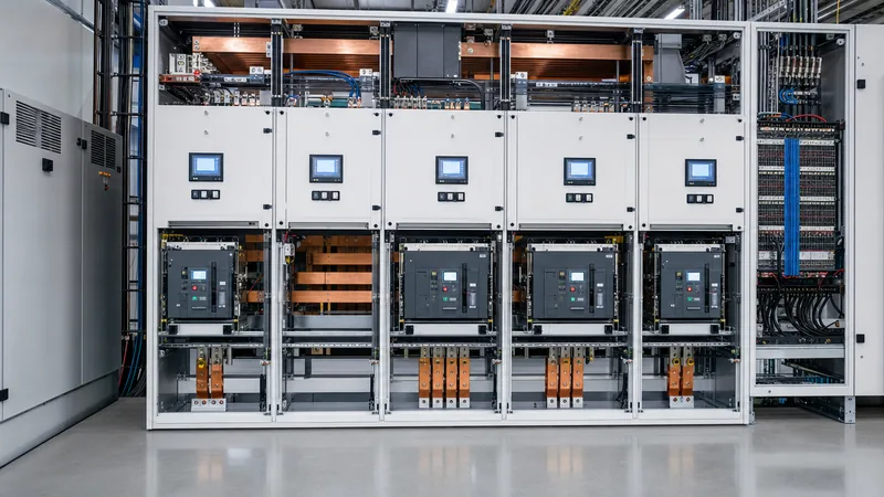
Core low voltage products comprise air circuit breakers (ACBs), moulded case circuit breakers (MCCBs), fuse-switch disconnectors, and multi-function metering units assembled within tested switchboards. In a secondary packaged substation or factory switchroom, these apparatus sit directly downstream of the medium-to-low voltage distribution transformer to establish a safe, switchable interface.
Primary circuit protection begins at the incomer. High-current ACBs (typically 800 A to 6,300 A) incorporate micro-processor trip units providing long-time (L), short-time (S), instantaneous (I), and ground-fault (G) protection per IEC 60947-2. Sub-distribution feeders utilise MCCBs or modular fuse combinations to supply motor control centres (MCCs), local control panels, or auxiliary services. Coordination between these primary switching elements ensures that localized faults trip only the immediate downstream device, maintaining system availability throughout the rest of the facility.
Low Voltage Distribution System Design: Sizing and Topologies
A low voltage distribution system delivers electrical energy from the secondary transformer terminals to facility branch circuits via radial, loop, or double-ended switchgear topologies. Selection of the topology depends directly on required reliability levels, allowable maintenance downtime, and prospective fault energy.
In standard industrial substations, radial feeds provide the most cost-effective solution, connecting a single transformer to an incoming breaker and distribution bus. However, critical infrastructure, data facilities, and process manufacturing generally adopt a secondary-selective (Main-Tie-Main) scheme. In this configuration, two independent transformers feed two switchboard halves joined by a normally open tie breaker. For in-depth principles of incoming feeder selection, review our guide to electric power distribution. Sizing of main busbars requires calculating full-load current ($I_n$) and selecting an electro-tin-plated copper cross-section capable of remaining below a temperature rise limit of 105 °C under continuous load, compliant with IEC 61439-1 Table 8.
Selecting the Right Low Voltage Distributor and Switchboard Forms
A low voltage distributor switchboard must provide structural segregation to safeguard operators and prevent fault propagation between functional units. IEC 61439-2 defines these internal separation boundaries as Forms 1 through 4b, which classify the barriers between busbars, functional devices, and termination terminals.
Understanding these forms is vital when specifying equipment for substations and factory floors:
- Form 1: No internal separation between busbars, devices, and connection terminals.
- Form 2b: Busbars are separated from functional units, and terminals are separated from the busbars.
- Form 3b: Busbars are separated from functional units, individual functional units are separated from each other, but terminals for external conductors are grouped together.
- Form 4b: Busbars are separated from functional units, all functional units are separated from one another, and outgoing termination chambers for each unit are completely segregated from other functional terminals.
For applications where uptime is mandatory, Form 4b withdrawable assemblies are standard practice. They allow technicians to rack out an MCCB or ACB for routine maintenance while adjacent compartments remain energised, preventing arc transfer or accidental busbar contact. Further design rules for low-voltage enclosures are detailed in our analysis of IEC 61439 switchgear.
Engineering Low Voltage Power Distribution: Worked Fault Current Calculation
Calculating prospective three-phase short-circuit fault current ($I_{sc}$) is essential to ensure low voltage power distribution equipment possesses sufficient short-circuit making and breaking capacity ($I_{cu}$ / $I_{cs}$).
Consider a standard secondary packaged substation housing a 1,600 kVA, 11 kV to 400 V distribution transformer with an impedance voltage ($u_k$) of 6.0%. Assuming an infinite medium-voltage source for worst-case analysis:
- Calculate Rated Secondary Current ($I_n$):
$$I_n = \frac{S}{\sqrt{3} \times V_{LL}} = \frac{1,600,000}{\sqrt{3} \times 400} = 2,309.4\text{ A}$$ - Calculate Symmetrical Fault Current at LV Terminals ($I_{sc}$):
$$I_{sc} = \frac{I_n}{u_k / 100} = \frac{2,309.4}{0.06} = 38,490\text{ A} \approx 38.5\text{ kA}$$ - Determine Peak Short-Circuit Withstand ($I_{pk}$):
Per IEC 61439-1 clause 9.3, the peak factor ($n$) for short-circuit currents between 20 kA and 50 kA with a typical system power factor of 0.25 is 2.1:
$$I_{pk} = I_{sc} \times n = 38.5\text{ kA} \times 2.1 = 80.85\text{ kA peak}$$
Consequently, the main incomer ACB, busbar supports, and structural bracing must be certified for a short-time withstand current ($I_{cw}$) of at least 40 kA for 1.0 second, and a dynamic peak withstand ($I_{pk}$) of at least 85 kA. Specifying components below these mechanical thresholds invites catastrophic busbar distortion and casing rupture during an actual short-circuit event.
Essential Low Voltage Devices: Technical Comparison Table
Essential low voltage devices fulfill specialized protective, switching, and monitoring roles within switchgear assemblies. Selecting the correct component depends on nominal current ratings, interrupt capacity, switching life, and physical layout limits.
| Device Type | Operating Current Range (A) | Standard Breaking Capacity ($I_{cu}$) | Primary IEC Standards | Typical Application in Substation |
|---|---|---|---|---|
| Air Circuit Breaker (ACB) | 630 A to 6,300 A | 50 kA to 150 kA | IEC 60947-2 | Main substation incomer and tie breaker |
| Moulded Case Circuit Breaker (MCCB) | 16 A to 1,600 A | 25 kA to 100 kA | IEC 60947-2 | Sub-distribution feeders, motor branch lines |
| Miniature Circuit Breaker (MCB) | 0.5 A to 125 A | 6 kA to 25 kA | IEC 60898-1 / 60947-2 | Control circuits, panel lighting, instrumentation |
| Switch Disconnector / Fuse-Switch | 32 A to 1,250 A | Up to 120 kA (with fuse) | IEC 60947-3 | Manual isolation, high-energy backup circuits |
| Surge Protective Device (SPD) | $I_n$: 20 kA to 40 kA (Type 1+2) | Up to 100 kA spark gap | IEC 61643-11 | Surge arrest at main low voltage incomer |
| Power Quality Meter | CT-driven (1 A or 5 A) | N/A (Sensing device) | IEC 61557-12 | Harmonic analysis, revenue billing, telemetry |
To examine downstream panel building practices and switchboard topologies in detail, consult our technical resource on SWBD electrical engineering.
Procurement and Factory Acceptance Checklist for Low Voltage Assemblies
Procuring factory-built low voltage assemblies requires rigorous verification of design verification reports and shop floor acceptance testing. The following checklist ensures incoming switchboards meet design parameters before site shipment:
- Verification of Temperature Rise Limits: Check type-test certificates verifying temperature rise per IEC 61439-1 clause 10.10. Ensure ambient correction factors are applied if site temperatures exceed 40 °C.
- Short-Circuit Withstand Certification: Validate that busbar assemblies possess certified test records matching the site calculated $I_{cw}$ and $I_{pk}$. Inspect clearance and creepage distances across busbar supports per IEC 61439-1 Table 1 and Table 2.
- Dielectric and Insulation Resistance Testing: Perform 1-minute power-frequency withstand tests at 1,890 V AC or 2,500 V DC for circuits rated 400 V nominal. Confirm insulation resistance exceeds 100 MΩ prior to and following dielectric testing.
- Protective Device Calibration and Trip Settings: Verify electronic trip units (LSIG) against the site power system study curves. Confirm secondary injection testing records for each ACB and MCCB.
- Degree of Ingress Protection (IP Rating): Inspect gasketing, ventilation louvres, and gland plates to verify compliance with specified ratings (typically standard indoor enclosure ratings for clean indoor switchrooms; heavy-duty weatherproof ratings for outdoor packaged substations).
Next steps: specifying and sourcing
When specifying and sourcing low voltage products for factory or utility distribution, compile your single-line diagram (SLD), prospective fault level calculations, required segregation form, and ambient operating parameters. Selecting factory-tested assemblies ensures seamless integration with upstream transformers and downstream motor control equipment. Explore our certified HV & LV switchgear solutions and complete transformer substations to match your project specifications. For rapid equipment sizing, customized enclosure engineering, or detailed pricing schedules, request a direct quotation from our engineering team.
Frequently asked questions
What is the voltage range defined for low voltage products?
Low voltage products are defined under IEC 60038 and IEC 60947 as electrical equipment operating up to 1,000 V AC or up to 1,500 V DC. In commercial and industrial facilities, the most common standard three-phase AC operating levels are 380 V, 400 V, 415 V, and 480 V.
What is the role of a low voltage distributor in a substation?
A low voltage distributor receives transformed electrical power from the transformer secondary terminals and subdivides it across multiple protected branch circuits. It integrates main air circuit breakers, busbar networks, protection relays, and metering equipment to ensure safe delivery to downstream switchboards.
What is the difference between an ACB and an MCCB?
Air circuit breakers (ACBs) are open-construction devices rated from 630 A to 6,300 A with high short-time withstand ratings (Icw), used mainly as incoming switchgear. Moulded case circuit breakers (MCCBs) are compact, enclosed devices rated up to 1,600 A, designed primarily for branch circuit and feeder protection.
Why is IEC 61439 certification mandatory for low voltage switchgear?
IEC 61439 certification verifies that low voltage switchgear assemblies have passed design verification for temperature rise limits, dielectric properties, short-circuit withstand strength, and protective circuit continuity. It eliminates self-certification and guarantees that assemblies operate safely under stated design loads.
How does Form 4b separation enhance operational safety?
Form 4b separation isolates horizontal and vertical busbars from functional units, separates each functional unit from others, and completely isolates individual cable termination compartments. This prevents electrical arcs or dropped tools from causing multi-circuit flashovers, permitting safe maintenance while adjacent units stay live.
Tags: low voltage products low voltage distributor low voltage distribution system low voltage power distribution low voltage devices


