Key takeaways
- A generator transformer steps up medium-voltage alternator output (typically 11 kV to 25 kV) directly to high-voltage transmission levels up to 500 kV or higher.
- GSU stands for Generator Step-Up, representing the critical electrical bridge operating under continuous baseload thermal and magnetic stress in utility power stations.
- Standard short-circuit impedance (%Z) for generator step-up units ranges between 10% and 18% to balance fault current limitation against grid transient stability.
- Low-voltage windings in a generator transformer are predominantly delta-connected to trap third-harmonic currents and isolate the generator from grid zero-sequence ground faults.
- Forced cooling classifications such as OFAF or ODAF are standard for large generator transformers to manage continuous winding hotspot temperatures in accordance with IEC 60076-2.
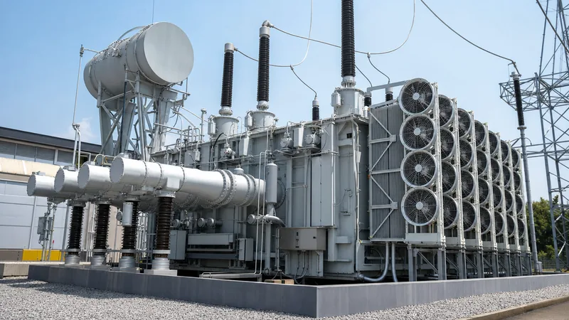
Quick answer: A generator transformer (commonly designated as a generator step-up or GSU transformer) is a heavy-duty power transformer engineered to step up the medium output voltage of a power station alternator—typically 11 kV to 25 kV—to high-voltage or extra-high-voltage transmission levels between 110 kV and 765 kV for long-distance bulk power delivery.
In thermal, hydroelectric, nuclear, and large-scale combined-cycle generating stations, the generator transformer serves as the single primary conduit through which megawatt-scale generation enters the electrical utility grid. Unlike standard network distribution units that experience cyclic loading profiles, a generator transformer operates at or near full thermal capacity for weeks or months at a stretch. A failure at this node completely disconnects the generating turbine from the grid, incurring severe commercial and stability repercussions. Sizing and specifying this equipment requires deep consideration of fault current withstand, flux density, continuous harmonic loading, and system stability as detailed in our broader power plant transformer engineering guide.
What does GSU stand for transformer installations?
In electrical engineering, GSU stands for Generator Step-Up transformer, which identifies the specialized high-voltage transformer directly tied to the terminals of an electrical turbine generator.
When engineers ask what does gsu stand for transformer equipment, they are referring to the specific plant position that increases the alternator's native generation voltage up to the grid transmission voltage. Alternators cannot economically generate electricity directly at high transmission voltages such as 275 kV or 400 kV because high-voltage stator slot insulation would require stator dimensions and magnetic air gaps that are mechanically and physically impractical. Consequently, generators produce power at moderate voltages (usually between 10.5 kV and 24 kV) and high currents. The GSU transformer connects immediately downstream via isolated phase busbars (IPB) to convert this low-voltage, high-current generation into high-voltage, low-current bulk transmission power, drastically minimizing I²R resistive line losses across the transmission corridor. You can review how this interfaces with high-voltage utility networks in our transmission transformer engineering guide.
Winding configurations and vector groups for generator transformers
The standard vector group for a utility generator transformer is almost universally YNd11 or YNd1, pairing a delta-connected low-voltage winding with a star-connected, neutral-grounded high-voltage winding.
This specific configuration delivers critical operational and protective advantages:
- Third Harmonic Suppression: The delta connection on the generator side provides a closed circulating path for third-harmonic zero-sequence currents generated by synchronous machines. This prevents harmonic voltages from propagating onto the utility transmission line and distorting the grid waveform.
- Zero-Sequence Isolation: The delta winding acts as a barrier that prevents zero-sequence currents caused by external phase-to-ground faults on the high-voltage transmission line from reflecting onto the generator terminals, protecting the generator rotor and stator from unbalanced thermal stresses.
- Solid Grounding Capability: The wye connection on the high-voltage (transmission) side provides an accessible neutral terminal that can be solidly grounded or grounded through a low-impedance neutral reactor, stabilizing system neutral voltage and enabling sensitive earth-fault detection.
- Phase Angle Displacement: Vector group YNd11 introduces a 30-degree lead, whereas YNd1 introduces a 30-degree lag; the selection depends entirely on grid synchronization matching and system bus phase standards.
For more details on core construction and coil layouts that support these connections, refer to our guide on step-up transformer engineering principles.
Key technical specifications and engineering parameters
Specifying a generator transformer requires exact alignment with generator capability curves, grid interconnection codes, and short-circuit impedance parameters per IEC 60076 and IEEE C57.12.00.
Because GSU units operate under continuous rated load, core magnetic flux densities are typically constrained between 1.6 Tesla and 1.7 Tesla to prevent excessive core heating during generator voltage fluctuations and system load rejection events. Short-circuit impedance (%Z) is a deliberate design compromise: lower impedance reduces reactive power losses and improves system stability margins, but increases prospective short-circuit fault currents that mechanical structures, circuit breakers, and switchgear must withstand.
| Engineering Parameter | Typical Range / Rating | Governing Standard | Design Considerations |
|---|---|---|---|
| Power Rating (MVA) | 50 MVA to 1,200 MVA | IEC 60076-1 / IEEE C57.12.00 | Must match 100% to 110% of continuous generator gross output MVA. |
| LV Voltage Rating (kV) | 10.5 kV to 25 kV | IEC 60076-3 / IEEE C57.12.00 | Matches turbine generator terminal voltage; high continuous current. |
| HV Voltage Rating (kV) | 110 kV to 765 kV | IEC 60076-3 / IEEE C57.12.00 | Matches grid transmission substation interconnection bus voltage. |
| Impedance (%Z) | 10.0% to 18.0% | IEC 60076-1 / IEEE C57.12.90 | Balances fault current limitation against machine transient stability. |
| Cooling Classification | ONAN / ONAF / OFAF / ODAF | IEC 60076-2 / IEEE C57.12.00 | Forced directional oil flow (ODAF) preferred on units above 300 MVA. |
| Vector Group | YNd11 or YNd1 | IEC 60076-1 / IEEE C57.12.70 | Delta on generator side (LV), wye-grounded on grid side (HV). |
| Basic Impulse Level (BIL) | 550 kV to 2,050 kV | IEC 60076-3 / IEEE C57.12.00 | Determined by HV transmission insulation co-ordination and lightning surge protection. |
| Tap Changer Configuration | DETC (±2×2.5%) or OLTC | IEC 60214 / IEEE C57.131 | De-energised tap changers (DETC) common; OLTC used if grid voltage swings widely. |
Thermal dynamics and forced cooling systems
Generator step-up transformers rely on multi-stage forced cooling systems to dissipate the immense heat generated by full-load currents exceeding several thousand amperes on low-voltage windings.
Under IEC 60076-2, temperature rises are strictly limited—typically 65 K for top oil and 70 K or 78 K for average winding rise, depending on insulation material class (Kraft paper versus thermally upgraded paper). Cooling systems are classified using four-letter designations:
- ONAN/ONAF: Oil Natural Air Natural transitioning to Oil Natural Air Forced via radiator banks equipped with electric fans. Suitable for smaller generator step-up transformers up to approximately 100 MVA.
- OFAF: Oil Forced Air Forced, incorporating internal circulating pumps that accelerate bulk oil circulation across the core and coils, discharging thermal loads through forced-air radiator banks.
- ODAF: Oil Directed Air Forced, the industry benchmark for heavy utility GSUs exceeding 250 MVA. Internal baffles and ducts route cooled oil directly through the winding conductors, preventing localized hotspots and maintaining temperature uniformity across high-current conductor paths.
- OFWF: Oil Forced Water Forced, frequently deployed in hydroelectric caverns or compact coastal installations where clean cooling water is abundant and space for external air-cooled radiator banks is restricted.
Protection coordination and withstand requirements
Generator transformers require dedicated multi-zone electrical protection schemes to mitigate both internal winding defects and external transmission network abnormalities.
Because GSU units directly couple generating units to long-distance lines, they are subject to severe electrical disturbances, including out-of-phase synchronisation shocks, full-load rejections, lightning surges, and back-fed grid short circuits. Key protective relay schemes must be coordinated in accordance with engineering principles outlined in our substation transformer protection engineering guide:
- Overall Unit Differential Protection (ANSI 87U): Covers both the generator and the GSU within a single zone, utilizing harmonic restraint filtering to prevent nuisance tripping caused by high transformer magnetising inrush currents.
- Transformer Differential Protection (ANSI 87T): Dedicated differential relay encompassing only the GSU transformer terminals, calibrated for high-speed tripping during internal turn-to-turn or phase-to-phase insulation breakdown.
- Overexcitation / Volts-per-Hertz Protection (ANSI 24): Protects against core saturation and destructive heating caused by abnormal voltage-to-frequency ratios ($V/f > 1.05\text{ to }1.10\text{ p.u.}$), which regularly occur during sudden turbine load rejections or generator startup before synchronization.
- Restricted Earth Fault (ANSI 87N/REF): Delivers high-sensitivity ground fault detection for the high-voltage wye winding, detecting faults near the neutral point where standard differential elements lack sensitivity.
- Buchholz and Pressure Relief Relays (ANSI 63): Mechanical protection devices that sense gas accumulation, oil surges, and catastrophic overpressures within the oil tank resulting from internal arcing faults.
Step-by-step sizing and specification procedure
Correctly sizing a generator transformer involves an iterative engineering process that integrates alternator output capacity, ambient derating, and auxiliary load requirements.
- Determine Turbine Maximum Continuous Rating (MCR): Identify the peak active power ($P$) output of the turbine generator in megawatts and calculate gross MVA using the rated generator power factor ($\cos\phi$, typically 0.80 to 0.85 lagging):$$\text{Gross MVA} = \frac{P}{\cos\phi}$$
- Account for Auxiliary Plant Loads: If the unit auxiliary transformer (UAT) taps directly from the generator terminals ahead of the GSU low-voltage bushings, subtract the maximum auxiliary station load from the total capacity to establish the net power export delivered to the GSU.
- Apply Ambient and Site Derating Factors: Apply derating coefficients per IEC 60076-2 for ambient air temperatures exceeding 40°C, high solar radiation, or installations at altitudes greater than 1,000 meters above sea level where thin air reduces dielectric strength and convective heat dissipation.
- Establish Short-Circuit Impedance (%Z): Coordinate with the transmission system operator (TSO) through load-flow and short-circuit studies to select an impedance that confines bus fault currents within substation switchgear breaking ratings without degrading generator transient stability margins.
- Select Tap Changer Architecture: Determine whether a De-Energised Tap Changer (DETC, e.g., $\pm 2 \times 2.5\%$) is sufficient for steady baseload facilities, or if an On-Load Tap Changer (OLTC) is mandatory due to extreme seasonal transmission grid voltage swings.
- Define Insulation and Transient BIL Levels: Coordinate Basic Impulse Insulation Levels (BIL) and Switching Impulse Levels (SIL) based on transmission substation surge arrester characteristics and system insulation co-ordination standards.
Next steps: specifying and sourcing
When preparing technical specifications for a generator transformer project, compile your single-line diagrams, generator capability curves, site environmental extremes, transmission voltage variation limits, and loss capitalisation formulae ($A$ and $B$ evaluation factors for no-load and load losses). Our engineering team designs and manufactures utility-grade power transformers and severe-duty oil-immersed transformers engineered to IEC 60076, IEEE C57, and customer-specific grid interconnection standards. Contact our application engineers through our transformer quotation portal to review your project data sheets and obtain detailed design proposals.
Frequently asked questions
what does gsu stand for transformer
GSU stands for Generator Step-Up transformer. It is the primary electrical transformer in a power station that steps up medium generation voltage (typically 11 kV to 25 kV) to high-voltage transmission levels (such as 110 kV, 220 kV, or 400 kV) for bulk power delivery to the electrical grid.
Why is the low-voltage winding of a generator transformer connected in delta?
The low-voltage winding is connected in delta to trap third-harmonic currents produced by the generator, preventing them from distorting the transmission grid. Additionally, the delta configuration isolates the generator from zero-sequence currents caused by ground faults on the high-voltage transmission system.
What is the typical impedance of a generator transformer?
The short-circuit impedance of a generator transformer typically ranges from 10% to 18%. This value is selected to limit prospective short-circuit fault currents while maintaining sufficient electromagnetic coupling to preserve the generator's transient and steady-state stability during grid disturbances.
Does a generator transformer need an on-load tap changer (OLTC)?
Most baseload generator step-up transformers utilize de-energized tap changers (DETC) rather than OLTCs because generator excitation control can adjust terminal voltage by ±5% to ±10%. However, an OLTC is specified if regional transmission grid voltages fluctuate severely or if local grid interconnection codes strictly mandate independent reactive power control.
What causes overexcitation in a generator step-up transformer?
Overexcitation occurs when the ratio of operating voltage to operating frequency (Volts/Hertz) exceeds the transformer's continuous magnetic design rating, typically above 1.05 to 1.10 per unit. This condition commonly happens during sudden full-load rejections or during turbine startup and shutdown if full field excitation is applied at reduced turbine speed.
How does a generator transformer differ from a standard transmission substation transformer?
A generator transformer is designed for continuous unidirectional power flow at near-maximum rated capacity, experiences high continuous low-voltage currents, and must withstand frequent mechanical vibration and flux variations. Transmission substation transformers experience cyclic bidirectional loading, lower current density on both sides, and generally handle variable power flows between interconnected networks.
Tags: generator transformer gsu transformer step-up transformer power transformers substation engineering


