Key takeaways
- A qualified electrical equipment manufacturer must prove compliance with IEC 60076 or IEEE C57.12.00 through accredited type test certificates from independent laboratories.
- Factory acceptance testing (FAT) for power transformers requires routine loss measurements per IEC 60076-1 clause 11.5 with tolerances strictly limited to +15% on individual losses and +10% on total losses.
- Evaluating manufacturing plant capabilities requires inspecting winding tension controls, vapour-phase drying vacuum levels below 0.1 mbar, and cleanroom air quality.
- Procurement contracts in the industrial electrical equipment industry must incorporate clear penalty structures for exceeding guaranteed no-load and load losses.
- Standardised Request for Quotation (RFQ) packages must state insulation classes, basic impulse level (BIL), short-circuit withstand capabilities, and site seismic ratings upfront.
Quick answer: Selecting an electrical equipment manufacturer requires auditing core technical competencies, verified compliance with international standards such as IEC 60076 or IEEE C57.12.00, and stringent factory acceptance testing. A tier-one supplier provides third-party type test reports, precision winding infrastructure, calibrated loss-measurement systems, and transparent material traceability for magnetic core steel and winding conductors.
Procurement teams and consulting engineers often face critical challenges when choosing an industrial supplier for medium-voltage (MV) and high-voltage (HV) installations. Sourcing transformers, switchgear, and modular substations involves severe operational risk; poor quality control or improper insulation engineering can cause unplanned grid outages, safety hazards, and substantial financial losses. In the modern global supply network, differentiating high-performing producers from mere assembly workshops requires looking past sales claims to examine verified engineering practices, metallurgical certifications, and factory tooling capabilities.
Core capabilities of an electrical equipment manufacturer
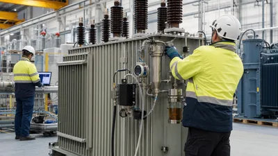
A reputable electrical equipment manufacturer maintains full control over design engineering, raw material processing, assembly, and quality verification. Within the industrial electrical equipment industry, reliable production is governed by rigorous manufacturing discipline rather than simple component assembly. For power apparatus such as oil-immersed or dry-type transformers, the plant must operate specialised machinery designed to handle heavy mechanical stresses and high-grade dielectric assemblies.
Key manufacturing capabilities include:
- Core cutting and stacking lines: Automated grain-oriented silicon steel (CRGO) cut-to-length lines with step-lap stacking reduce no-load excitation losses and core noise per IEC 60076-1 clause 5.4.
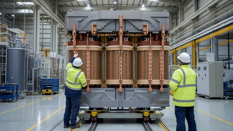
- Tension-controlled coil winding: Computer-controlled winding lathes maintain uniform tension on copper or aluminium conductors, preventing axial displacement during thermal cycling and external faults.
- Vapour-phase drying (VPD) plants: Advanced drying plants draw core-and-coil assemblies down to vacuum levels below 0.1 mbar at 110°C to 130°C, reducing residual moisture in solid insulation to below 0.5% by weight.
- Cleanroom active-part assembly: Enclosed, climate-controlled assembly bays prevent airborne dust and metallic particles from contaminating insulation barriers before tanking.
Engineers sourcing custom equipment should consult our custom transformer procurement guide to align mechanical footprint limits with winding configuration requirements.
Engineering standards in modern electrical manufacturing
Compliance with international standards separates reliable electrical manufacturing companies from marginal fabricators. Standardisation guarantees that apparatus will withstand continuous operational duty, dynamic short-circuit forces, and atmospheric surges without premature insulation degradation.
When evaluating an engineering submission, project managers must verify specific standard clauses:
- Dielectric withstand ratings: Insulation coordination must satisfy IEC 60076-3 or IEEE C57.12.00 Table 5, defining power-frequency withstand voltage and basic impulse level (BIL) ratings (e.g., 95 kV BIL for 24 kV systems; 170 kV BIL for 36 kV systems).
- Thermal rise limits: Temperature rise guarantees must adhere to IEC 60076-2, limiting average winding rise to 65 K for standard mineral oil or up to 100 K to 125 K for Class H systems, detailed further in our winding temperature guide.
- Short-circuit thermal and dynamic withstand: Calculations and test records must prove compliance with IEC 60076-5 clause 4, confirming that mechanical bracing withstands peak electromagnetic forces without conductor deformation.
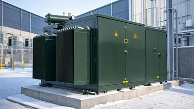
- Enclosure safety and ingress: Distribution substations and packaged switchgear must comply with IEC 62271-200 for internal arc classification (IAC) and IEC 60529 for ingress protection (IP ratings).
Audit criteria for industrial manufacturing electrical facilities
Facility audits provide the most dependable assessment of competence in industrial manufacturing electrical operations. Reviewing documentation is insufficient; engineering auditors must physically inspect the production floor, calibration records, and non-conformance quarantine procedures.
Use the following criteria when performing or commissioning a vendor quality audit:
| Audit Category | Specific Verification Focus | Acceptable Criteria / Industry Benchmark |
|---|---|---|
| Raw Material Integrity | Electrolytic copper and CRGO steel certificates | Conductivity ≥ 100% IACS for ETP copper; certified mill test sheets for core steel grade (e.g., laser-treated 23Q090 or Hi-B). |
| Winding Environment | Particulate count and relative humidity in winding shop | Positive pressure air handling; ambient relative humidity ≤ 45%; continuous particulate monitoring. |
| Insulation Processing | VPD parameters and oil filling plant | Vacuum capability ≤ 0.1 mbar; oil degassing to ≤ 5 ppm moisture and ≤ 0.5% dissolved air by volume. |
| Test Bay Calibration | Traceability of measurement instruments | Calibration certificates current within 12 months, traceable to national metrology institutes (ISO/IEC 17025 accredited). |
| Weld Quality & Painting | Transformer tank seams and surface protection | NDT leak testing under 50 kPa positive pressure for 24 hours; heavy-duty marine-grade multi-coat paint systems per ISO 12944. |
Total cost of ownership and loss evaluation formulas
Evaluating quotations from an electrical equipment manufacturer purely on initial capital expenditure leads to inflated operational lifecycle expenses. High-voltage power apparatus incurs continuous electrical losses over operating lifespans that frequently exceed 30 years. Modern engineering bids require loss capitalisation formulas to evaluate the real economic cost.
Total Owning Cost (TOC) is evaluated using standard capitalisation values for no-load (core) and load (copper) losses per the following formula:
TOC = Purchase Price + (A × P0) + (B × Pk)
Where:
- P0: Guaranteed no-load loss at rated voltage and frequency (kW).
- Pk: Guaranteed load loss at rated current and reference temperature (kW).
- A: Capitalisation value of no-load losses (£/kW or $/kW), reflecting continuous 8,760 hours/year energisation.
- B: Capitalisation value of load losses (£/kW or $/kW), adjusted for plant loading factor.
Consider a practical purchasing calculation for a 2,500 kVA, 11 kV / 400 V distribution unit with A = £6,500/kW and B = £2,200/kW:
- Manufacturer X: Quoted price = £38,000; P0 = 2.4 kW; Pk = 21.0 kW.
TOC = £38,000 + (6,500 × 2.4) + (2,200 × 21.0) = £38,000 + £15,600 + £46,200 = £99,800 - Manufacturer Y: Quoted price = £44,000; P0 = 1.7 kW; Pk = 18.5 kW.
TOC = £44,000 + (6,500 × 1.7) + (2,200 × 18.5) = £44,000 + £11,050 + £40,700 = £95,750
Although Manufacturer Y is £6,000 more expensive up front, superior efficiency yields a net lifecycle saving of £4,050. Furthermore, contracts must stipulate commercial penalties per IEC 60076-1 clause 10 if actual factory losses exceed quoted figures during witnessing.
Factory acceptance testing and verification procedures
Factory Acceptance Testing (FAT) validates that manufactured equipment conforms strictly to design guarantees and regulatory standards before it departs the factory gate. Buyers must never waive FAT or accept unverified, internal factory certificates without witness supervision.
A comprehensive FAT follows a systematic sequence carried out in an electrically shielded test bay:
- Winding resistance measurement: Performed across all tap positions using a four-wire Kelvin bridge per IEC 60076-1 clause 11.2 to verify conductor cross-section and identify loose internal connections.
- Voltage ratio and vector group verification: Testing turns ratio and phase displacement across all taps to ensure accurate polarity and vector alignment per clause 11.3.
- No-load loss and excitation current test: Energising the low-voltage winding at rated sinusoidal frequency while measuring power draw and current distortion per clause 11.5.
- Short-circuit impedance and load loss test: Circulating rated current through the short-circuited windings at ambient temperature, mathematically correcting values to reference temperature (e.g., 75°C) per clause 11.4.
- Dielectric routine testing: Applying separate-source power-frequency AC withstand voltage (e.g., 50 kV for 1 minute on 24 kV systems) and induced overvoltage testing at twice rated voltage and double frequency per IEC 60076-3.
- Partial discharge (PD) measurement: Verifying that PD levels remain below 10 pC for dry-type units or 100 pC for liquid-filled power transformers at 1.58 Um/√3.
For complex high-voltage contracts, refer to our comprehensive guide on power transformer testing for complete acceptance thresholds.
Procurement checklist for technical specifications
Ambiguity in tender documentation leads to manufacturing compromises and costly variation claims. When issuing technical specifications in the electrical manufacturing sector, engineering teams should incorporate a structured checklist directly into their procurement documents.
Essential parameters to specify include:
- Operating environment: Minimum and maximum ambient temperature (-25°C to +50°C), maximum altitude above sea level (> 1,000 m requires insulation derating per IEC 60076-1), and atmospheric corrosivity category (C1 through C5 per ISO 12944).
- Electrical system ratings: Nominal primary/secondary voltages, tap range (e.g., ±2 × 2.5% off-circuit or On-Load Tap Changer), frequency (50 Hz / 60 Hz), and BIL rating.
- Short-circuit capacity: Available network fault level (kA or MVA) and fault duration (typically 2.0 or 3.0 seconds) that the windings must withstand.
- Cooling designation: Specify ONAN, ONAF, KNAN (synthetic ester), or AN/AF per cooling requirements.
- Protection accessories: Exact requirements for multi-contact Buchholz relays, magnetic oil level gauges, winding temperature indicators with 4-20 mA analogue transducers, and pressure relief devices with directional discharge pipes.
For turnkey industrial substations, engineers should review the mechanical layout considerations detailed in our unit substation engineering guide before finalising civil interfaces.
Next steps: specifying and sourcing
Securing high-reliability power equipment requires precise technical schedules and rigorous factory vetting. When preparing your inquiry, assemble single-line diagrams, site environmental profiles, loss evaluation criteria, and required protection device schedules. Our factory engineering team designs and manufactures equipment compliant with IEC, ANSI/IEEE, and EN standards. Explore our specialised power transformers, custom oil-immersed transformers, and integrated HV/LV switchgear solutions. To submit tender specifications, review type test records, or schedule a technical project consultation, reach out directly through our quotation inquiry page or connect with our engineering department via our contact page.
Frequently asked questions
What makes an electrical equipment manufacturer qualified for utility projects?
A qualified manufacturer holds valid ISO 9001, ISO 14001, and ISO 45001 accreditations, alongside certified type test reports from independent testing bodies. They must demonstrate in-house design engineering, climate-controlled winding facilities, automated vacuum drying, and calibrated, shielded routine test bays.
How do electrical manufacturing companies calculate transformer load losses?
Manufacturers measure load losses during factory testing by circulating rated current through one winding while short-circuiting the other. The measured power represents I²R losses plus stray and eddy losses, which are mathematically corrected to standard reference temperatures (typically 75°C or 85°C) per IEC 60076-1.
What are the allowed loss tolerances under IEC 60076-1?
IEC 60076-1 Table 1 sets standard tolerances at +15% for individual no-load or load losses, provided that the total combined loss does not exceed +10%. Exceeding these thresholds during witness testing typically triggers contractual financial penalties or unit rejection.
Why is vapour-phase drying essential in electrical equipment manufacturing?
Vapour-phase drying extracts moisture from solid cellulose insulation down to less than 0.5% moisture content by weight under deep vacuum (≤ 0.1 mbar). Inadequate drying accelerates thermal ageing, causes partial discharge, and drastically degrades the dielectric breakdown strength of the insulating fluid.
What documentation should accompany electrical equipment shipments?
Shipments must include certified factory acceptance test (FAT) reports, material mill certificates, operation and maintenance manuals, general arrangement drawings, schematic wiring diagrams, and shipping impact recorder logs to confirm zero transit shock damage.
Tags: electrical equipment manufacturer electrical manufacturing industrial manufacturing electrical industrial electrical equipment industry electrical manufacturing companies