Key takeaways
- In industrial procurement, diecast transformers refer to dry-type transformers built with vacuum-cast epoxy resin windings or precision high-pressure die-cast structural housings.
- Cast resin transformer coils encapsulated under vacuum achieve partial discharge levels below 10 pC at 1.3 times rated phase-to-ground voltage according to IEC 60076-11 clause 22.
- Die-cast aluminium terminal enclosures provide IP54 to IP66 ingress protection while reducing overall assembly weight by up to 40% compared to folded mild steel.
- Specifying Class F (155°C) or Class H (180°C) insulation with an 80K to 100K winding temperature rise guarantees extended insulation service life exceeding 25 to 30 years.
- Routine factory acceptance testing must verify insulation resistance, voltage ratio, winding resistance, short-circuit impedance, and partial discharge before dispatch.
Quick answer: In power distribution procurement, diecast transformers refers to solid-dielectric dry-type transformers encapsulated using precision vacuum casting moulds, as well as units featuring high-pressure die-cast structural components such as terminal boxes and bushing plates. Engineered to IEC 60076-11 and IEEE C57.12.01 standards, these transformers eliminate liquid dielectric hazards, deliver partial discharge levels under 10 pC, and provide fire-safe power distribution up to 35 kV.
Procurement teams and electrical consultants frequently encounter the terms diecast transformers and die cast transformers across tender specifications, equipment bills of materials, and international supplier catalogues. While non-technical search queries sometimes conflate toy replicas with power apparatus, electrical project engineers use the term to designate industrial cast resin transformers manufactured via die-moulding processes, or robust distribution units configured with precision die-cast light-alloy enclosures. For comprehensive technical background on general solid-cast systems, consult our dry-type transformer guide.
Selecting the correct unit requires understanding the physical boundary between structural die casting and electromagnetic vacuum resin casting. Specifying engineers must evaluate insulation classes, partial discharge thresholds, short-circuit electromechanical withstand, and environmental classifications (E2, C2, F1) to ensure asset longevity in commercial buildings, offshore platforms, data centres, and heavy manufacturing plants.
Understanding Diecast Transformers in Electrical Engineering
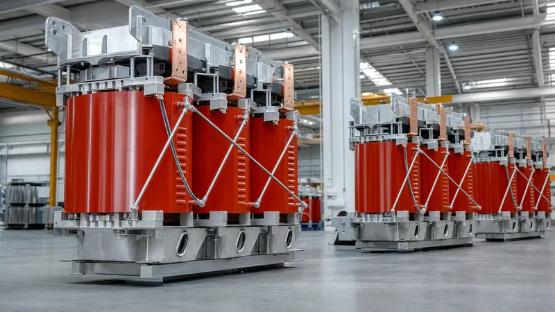
Diecast transformers combine precision casting metallurgy for structural components with high-vacuum epoxy mould casting for electromagnetic active parts. In high-voltage (HV) winding manufacturing, pre-formed coil assemblies are placed inside precision metallic casting dies, heated in an oven, and vacuum-impregnated with a hot mixture of epoxy resin, hardener, and silica quartz filler.
The resin mixture flows into every inter-turn and inter-layer void under a vacuum pressure of less than 2 mbar, preventing atmospheric entrapment. Concurrently, external auxiliary enclosures—such as marshalling boxes, cable-sealing glands, tap-changer covers, and low-voltage (LV) busbar supports—are manufactured from high-pressure die-cast aluminium alloys (such as standard casting alloys). These die-cast components deliver dimensional tolerances within ISO 2768-m, high galvanic corrosion resistance, and rigid mechanical enclosures rated up to IK10 impact resistance.
When consulting our electrical equipment manufacturer selection guide, engineers should confirm whether an OEM maintains both automated casting autoclaves for active winding dies and computerised numerical control (CNC) machining lines for die-cast hardware. This dual-casting discipline ensures that mechanical stress during three-phase symmetrical short circuits does not transfer destructive forces to the brittle solid-state insulation.
Engineering Specifications: Die Cast Transformers vs Traditional Types
Die cast transformers provide distinct dielectric, environmental, and maintenance advantages over traditional liquid-immersed and open-ventilated dry-type alternatives. Because the conductors are permanently sealed inside a monolithic resin block, the core-and-coil assembly resists moisture penetration, industrial chemical atmospheres, and fungal growth without requiring conservator tanks or liquid containment bunds.
The following engineering comparison highlights the functional parameters governing solid-cast equipment against traditional fluid-filled and vacuum-pressure impregnated (VPI) units:
| Engineering Parameter | Diecast / Cast Resin Unit | VPI Dry-Type | Mineral Oil Immersed |
|---|---|---|---|
| Standard Reference | IEC 60076-11 / IEEE C57.12.01 | IEC 60076-11 / IEEE C57.94 | IEC 60076-2 / IEEE C57.12.00 |
| Insulation Thermal Class | Class F (155°C) or H (180°C) | Class H (180°C) or C (220°C) | Class A (105°C) |
| Partial Discharge at 1.3× Um | < 10 pC | Typically < 50 pC | Not applicable (< 5 pC) |
| Fire Safety Classification | F1 (Self-extinguishing) | F0 / F1 (Design-dependent) | Requires Deluge / Bunding |
| Enclosure Ingress (Die-Cast Parts) | IP23 to IP66 | IP20 to IP33 | IP55 / IP65 Hermetic Tank |
| Environmental / Climatic Class | E2, C2 (Condensation / -25°C) | E0 / E1, C1 | Outdoor Severe Marine |
| Maintenance Interval | Annual visual / thermographic | Semi-annual cleaning/vacuum | Regular DGA / oil sampling |
Unlike fluid-immersed units, cast resin systems can be positioned inside populated commercial basements and high-rise service shafts without firewalls or blast relief basins, satisfying NFPA 70 (National Electrical Code) Article 450 requirements. For projects requiring fluid cooling for outdoor utility installations, consider our oil-immersed transformer solutions alongside indoor cast substations.
Thermal Performance and Winding Encapsulation Technology
Winding encapsulation in modern diecast transformers relies on epoxy resin systems blended with aluminium trihydrate and micro-silica powder. This formulation achieves a coefficient of thermal expansion (CTE) around 30 to 35 × 10⁻⁶ /K, closely matching the thermal expansion of electrical-grade copper (16.5 × 10⁻⁶ /K) or aluminium (23 × 10⁻⁶ /K) windings. Matching these coefficients prevents internal thermal shear stress and surface micro-cracking across cyclic duty variations.
Thermal design follows IEC 60076-11 Table 2, defining maximum temperature limits based on insulation classification:
- Class F Insulation System: Maximum permitted continuous hot-spot temperature is 155°C, based on a 40°C ambient reference and a 100K average winding temperature rise limit.
- Class H Insulation System: Maximum continuous hot-spot temperature is 180°C, permitting a 125K winding temperature rise, suited for high-density mining applications and marine vessel switchboards.
- Forced-Air Cooling Uplift (AF): Integrating temperature-controlled axial cross-flow fans beneath the winding coils increases continuous throughput capacity by 33% to 40% above natural-air (AN) ratings without exceeding internal Class F thermal thresholds.
Temperature monitoring is executed via PT100 platinum resistance sensors embedded directly inside the central low-voltage winding phases during coil winding. These transducers feed real-time temperature signals to an external, die-cast control terminal monitor that automatically triggers two-stage alarm and trip auxiliary relays.
Calculated Example: Sizing and Losses for a Cast Resin Transformer
Accurate sizing requires calculating active and reactive loading alongside short-circuit current stresses to verify the thermal-mechanical withstand of diecast transformers. Consider an industrial manufacturing facility requiring a step-down transformer to feed motor control centres and automation racks.
Design Inputs:
- Connected Maximum Load: P = 1,250 kW at cos φ = 0.85 lagging.
- Primary High Voltage (HV): 11,000 V (11 kV), three-phase, 50 Hz.
- Secondary Low Voltage (LV): 415 V line-to-line (240 V line-to-neutral).
- Specified Percent Impedance (%Z): 6.0% at reference temperature (120°C).
- Future expansion contingency factor: 1.15 (15% reserve margin).
Step 1: Calculate the Required Apparent Power Rating (S)
The initial apparent power load is calculated as:
Sload = P / cos φ = 1,250 kW / 0.85 = 1,470.58 kVA.
Applying the 15% future expansion margin:
Srequired = 1,470.58 × 1.15 = 1,691.17 kVA.
Select the next standard commercial rating according to IEC preferred sizes: 2,000 kVA.
Step 2: Calculate Rated Secondary Current (Ir, LV)
Ir, LV = Srated / (√3 × VLV) = 2,000,000 VA / (1.732 × 415 V) = 2,782.5 A.
Step 3: Calculate Prospective Symmetrical Short-Circuit Fault Current (Isc)
Assuming an infinite primary utility bus for worst-case evaluation:
Isc = Ir, LV / (%Z / 100) = 2,782.5 A / 0.06 = 46,375 A (46.38 kA).
The diecast coil structure, resin clamping plates, and die-cast terminal bus supports must withstand an initial peak dynamic current (Ipk = 46.38 kA × 2.55 = 118.27 kA) without mechanical deformation or insulation delamination, meeting IEC 60076-5 dynamic short-circuit withstand criteria.
Procurement and Factory Acceptance Testing Checklist
A comprehensive procurement specification protects asset operators from manufacturing defects, voids, and premature insulation aging in diecast transformers. When requesting bids from transformer factories, integrate this detailed inspection schedule into the commercial RFQ package.
Engineers can reference our specialised guide on power transformer testing to understand factory routine, type, and special test procedures. Use the following structured checklist during tender specification and Factory Acceptance Testing (FAT):
- Dielectric and Insulation Checks: Verify winding resistance across all taps (HV and LV), voltage ratio error within ±0.5%, and vector group displacement according to IEC 60076-1 clause 9. Perform core-to-frame insulation resistance testing using a 2,500 V megohmmeter (minimum acceptable value: 1,000 MΩ).
- Partial Discharge (PD) Measurement: Carry out PD testing per IEC 60076-11 clause 22. Apply prestressing voltage of 1.8 × Ur for 30 seconds, followed by measurement at 1.3 × Ur. Inception and extinction values must be recorded; background test cell noise must remain below 5 pC, and transformer internal discharge must not exceed 10 pC.
- Induced Overvoltage and Separate Source AC Withstand: Verify separate source power-frequency withstand (e.g. 28 kV RMS for 11 kV windings) for 60 seconds. Apply induced overvoltage at twice rated secondary voltage at 100 Hz or 200 Hz for 60 seconds to stress inter-turn insulation.
- No-Load and Full-Load Loss Verification: Measure core losses (P0) at 100% rated excitation voltage, and load losses (Pk) at rated current, corrected to reference temperature (120°C for Class F). Losses must comply with Ecodesign Tier 2 (EN 50588-1) or customer capitalisation loss guarantee formulas without positive tolerance penalties.
- Mechanical and Die-Cast Enclosure Audit: Inspect paint thickness (minimum 80 μm polyester powder coat on die-cast parts), verifying IP classification (standard indoor, IP54 outdoor) and torque markings on high-tensile tie-rods. Ensure low-voltage neutral grounding straps and terminal connection pads meet phase clearance distances.
Installation, Environmental Siting, and Maintenance Best Practices
Proper siting and installation dictate the long-term reliability of die cast transformers in harsh operating environments. Units specified for indoor industrial service must have unimpeded ventilation pathways; maintaining at least 500 mm clearance between the enclosure louvres and surrounding substation civil walls is essential for convective air currents.
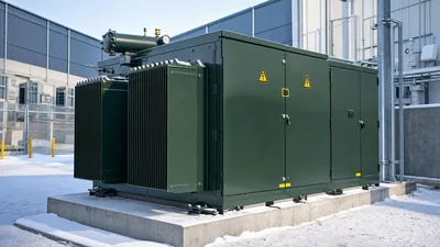
When deploying units into containerised systems or prefabricated housings, review our engineering rules for integrated compact transformer substations. Ambient intake air temperatures should remain within -25°C to +40°C. For installations subject to heavy condensation, coastal sea spray, or chemical airborne salts, specify an E2 environmental rating and install thermostatically controlled anti-condensation space heaters inside the die-cast LV enclosure.
Maintenance requirements for cast resin units are minimal compared to liquid assets. Scheduled annual shutdowns should involve visual inspections for surface dirt accumulation, cleaning resin cast surfaces using lint-free dry cloths and industrial vacuum equipment, and conducting thermographic scanning across high-current cable bolted interfaces under normal operating loads.
Next steps: specifying and sourcing
When preparing an inquiry for diecast transformers, compile your single-line diagram, nominal primary and secondary voltages, BIL ratings, vector configuration (such as Dyn11), enclosure IP code, and environmental classification. Our engineering team designs and manufactures high-performance dry-type transformers and custom industrial distribution units tested to international IEC, ANSI/IEEE, and GOST standards. For tailored engineering evaluations or fast-turnaround tenders, submit your schedule of requirements through our transformer quote page or speak directly with our electrical engineering staff via the contact page.
Frequently asked questions
What are diecast transformers in commercial electrical systems?
Diecast transformers are solid-dielectric dry-type distribution transformers where high-voltage coils are cast in epoxy resin inside metallic moulds under high vacuum, or units built with precision die-cast aluminium structural components. They eliminate combustible insulating oils, delivering fire-safe power distribution.
What is the acceptable partial discharge level for cast resin transformers?
According to IEC 60076-11 clause 22, the maximum allowable partial discharge level for vacuum-cast resin transformers is 10 picocoulombs (pC) when tested at 1.3 times the rated phase-to-ground operating voltage.
How does forced-air cooling affect die cast transformer capacity?
Installing cross-flow forced-air (AF) cooling fans along the base of cast resin windings increases continuous load-carrying capacity by 33% to 40% above the natural convection (AN) rating without exceeding standard Class F winding temperature limits.
Can diecast transformers be installed outdoors?
Yes, diecast transformers can operate outdoors when housed in weatherproof enclosures rated IP44, IP54, or higher. Outdoor units typically include anti-condensation space heaters and severe marine-grade anti-corrosion protective coatings on all die-cast hardware.
What insulation classes are standard for cast resin dry-type transformers?
Standard cast resin dry-type transformers are manufactured with Class F (155°C) or Class H (180°C) insulation systems. Class F permits an average winding temperature rise of 100K, while Class H allows a 125K rise above ambient.
What is the difference between VPI and diecast vacuum cast transformers?
VPI (vacuum-pressure impregnated) transformers use varnished coils dried with open air channels between windings, whereas diecast vacuum-cast units encapsulate conductors completely within solid epoxy resin moulds, providing superior resistance to moisture, chemicals, and short-circuit mechanical forces.
Tags: diecast transformers die cast transformers cast resin transformer dry type transformer transformer procurement