Key takeaways
- A telephone pole transformer is an overhead distribution transformer engineered to step down medium-voltage utility power (typically 4.16 kV to 34.5 kV) to domestic and light commercial service voltages (such as 120/240 V split-phase or 400/230 V three-phase).
- Overhead transformers adhere mechanically to ANSI C57.12.20 or IEC 60076 standards, with tank designs incorporating mild steel or 304L stainless steel for coastal and corrosive environments.
- Completely Self-Protected (CSP) units integrate high-voltage expulsion weak links, internal secondary circuit breakers, and lightning arresters directly onto the tank, reducing external line hardware.
- A bank of two or three single-phase units can be pole-mounted to form open-delta, closed-delta, or wye-wye three-phase secondary distribution supplies.
- Correct mechanical pole-loading verification must account for transformer wet weight, wind shear, and tension loads under ANSI O5.1 and National Electrical Safety Code (NESC) clearance rules.
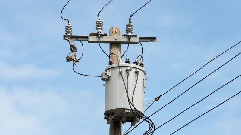
Quick answer: A telephone pole transformer is a pole-mounted, liquid-immersed distribution transformer that steps down medium-voltage distribution circuits (typically 11 kV, 13.8 kV, 24.94 kV, or 34.5 kV) to end-use secondary voltages such as 120/240 V split-phase or 400/230 V three-phase. Mounted directly on utility or joint-use telephone poles, these robust units supply residential, rural, and light commercial electrical services.
While common public parlance frequently uses the term telephone pole transformer, in electrical power distribution engineering these units are officially designated as an overhead transformer or a pole mounted distribution transformer. Utility poles frequently serve as joint-use infrastructure where telecommunications cables, fibre optics, and electrical power conductors share vertical clearance space. Positioned at the highest electrical level on the pole assembly, the transformer sits directly beneath the primary distribution feeders to ensure safe physical separation from lower-voltage communication lines. Understanding how to size, specify, and safely rig an electric pole transformer is vital for distribution network operators, industrial site planners, and engineering contractors deploying overhead medium-voltage infrastructure.
What Is an Electric Pole Transformer and How Does It Function?
An electric pole transformer is an oil-filled step-down electromagnetic machine designed for outdoor overhead installation on wooden, concrete, or steel utility structures. Its primary role within the power distribution grid is to bridge the gap between medium-voltage distribution networks and consumer load centres, minimising line losses over long rural or suburban spans while maintaining safe secondary terminal voltages.
The unit functions through classic mutual induction governed by Faraday’s law. The primary winding, connected to the medium-voltage overhead line via an expulsion fuse cutout or surge arrester, receives voltages ranging from 2.4 kV up to 34.5 kV line-to-line. The magnetic flux induced within the high-permeability silicon steel core links to the secondary winding, stepping the voltage down to standard utilisation levels. In North American and ANSI-based territories, this is predominantly a 120/240 V three-wire, single-phase, centre-tapped secondary. In IEC-based territories, these overhead units often step down three-phase distribution directly from 11 kV or 22 kV to 400/230 V four-wire services.
Because these units operate continuously under harsh environmental exposure, the active core and coil assembly is hermetically sealed within a cylindrical steel tank filled with dielectric insulating oil (inhibited mineral oil per IEC 60296 / ASTM D3487 or natural synthetic ester fluid). The fluid serves dual functions: providing electrical insulation across internal clearances and transferring heat generated by winding and core losses to the external tank wall via natural convection (cooling class ONAN). For wider network context on how these transformers interface with primary network designs, review our guide on electric power distribution engineering.
Core Configurations: Single-Phase Units vs Pole Transformer Banks
Overhead distribution systems employ either dedicated single-phase units, factory-assembled three-phase single-tank units, or multiple single-phase transformers banked together on a shared crossarm or cluster bracket. Sizing and configuration depend on load density, motor starting requirements, and primary system earthing.
For residential feeds, a single pole transformer rated between 15 kVA and 100 kVA provides 120/240 V split-phase power to several adjacent dwellings. When industrial or commercial consumers require three-phase power along an overhead corridor, electrical utilities install a pole distribution transformer bank using two or three single-phase units.
| Configuration Type | Number of Units | Primary Connection | Secondary Connection | Typical Capacity (kVA) | Common Industrial Application |
|---|---|---|---|---|---|
| Single-Phase Split-Phase | 1 | Phase-to-Neutral or Phase-to-Phase | Centre-Tapped 120/240 V | 10 to 167 kVA | Residential services, light single-phase commercial loads |
| Open-Delta (V-V) | 2 | Open Delta (Phase-to-Phase) | Open Delta (240 V 3-Phase + 120 V Lighting) | 2 x 25 to 2 x 75 kVA | Rural three-phase pump stations with unbalanced lighting loads |
| Closed Delta-Wye | 3 | Delta (3-Wire) | Wye with Neutral (480Y/277 V or 208Y/120 V) | 3 x 25 to 3 x 167 kVA | Commercial facilities, manufacturing shops, retail centres |
| Wye-Wye (Y-Y) | 3 | Grounded Wye (4-Wire) | Grounded Wye (480Y/277 V or 208Y/120 V) | 3 x 25 to 3 x 250 kVA | Modern standard utility overhead banks; suppresses ferroresonance |
| Three-Phase Single-Tank | 1 (Internal 3-phase core) | Delta or Wye | Wye or Delta (400 V or 480 V) | 30 to 500 kVA | Space-constrained urban settings, IEC-standard networks |
While an open-delta bank requires only two units—reducing upfront capital expenditure—it operates at only 57.7% of the capacity of three identical transformers and 86.6% of the combined rating of the two units. For facilities transitioning from overhead systems to compact ground infrastructure, comparing these overhead banks with a dedicated ground unit is essential, as detailed in our guide on unit substation engineering and sizing.
Internal Construction and Protection: Conventional vs CSP Utility Pole Transformers
A utility pole transformer is built as either a conventional transformer or a Completely Self-Protected (CSP) unit, with distinct internal architectures for overcurrent, overvoltage, and fault isolation.
Conventional overhead units rely entirely on externally mounted protective equipment. A primary porcelain or polymer expulsion fuse cutout is mounted to the pole crossarm above the primary high-voltage bushing, paired with a surge arrester connected to the incoming medium-voltage line. If an internal winding fault occurs, the cutout hinge drops open, providing visual confirmation of an isolated unit to line technicians.
Conversely, a CSP pole mounted transformer integrates the protective elements directly within or upon the transformer tank itself:
- Internal High-Voltage Weak Link: An internal expulsion fuse link is factory-installed in series with the primary winding to isolate the unit from the medium-voltage grid during an catastrophic internal dielectric breakdown, preventing feeder lockouts.
- Secondary Thermal Breaker: Mounted submerged inside the tank above the core, an internal low-voltage circuit breaker operates on an inverse-time thermal curve based on oil temperature and secondary load current, protecting the coils from downstream short circuits and prolonged secondary overloads.
- Tank-Mounted Surge Arresters: Direct-connected metal-oxide varistor (MOV) arresters are bolted directly to the tank adjacent to the primary bushings, providing ultra-short lead lengths that minimise inductive voltage drops during lightning strikes (in compliance with IEEE C57.12.20 clause 6.3).
- Emergency Overload Signal: An external indicator light illuminates when the internal oil reaches a predetermined thermal limit, alerting service crews before the breaker trips open.
Worked Engineering Calculation: Sizing and Voltage Drop for an Overhead Transformer
Accurate sizing of a transformer on power pole infrastructure requires evaluating peak diversified demand, rated winding current, short-circuit contribution, and regulatory voltage drop limits under full load.
Consider a light manufacturing workshop supplied by a single-phase 13,800 V to 240/120 V overhead transformer. The engineering load study indicates a diversified peak load of 42 kVA at 0.90 lagging power factor. The utility standard requires checking whether a standard 50 kVA transformer meets voltage drop criteria (not exceeding 2.5% internal impedance drop at rated load).
Step 1: Calculate full load secondary current ($I_{sec}$)
For a 50 kVA, 240 V secondary:
$$I_{sec} = \frac{S_{rated}}{V_{sec}} = \frac{50,000\text{ VA}}{240\text{ V}} = 208.33\text{ A}$$
Step 2: Determine full load primary current ($I_{pri}$)
$$I_{pri} = \frac{S_{rated}}{V_{pri}} = \frac{50,000\text{ VA}}{13,800\text{ V}} = 3.62\text{ A}$$
Step 3: Calculate prospective secondary fault current ($I_{sc}$)
Using standard nameplate impedance per IEEE C57.12.20 Table 3, assume percent impedance ($%Z$) is 2.1% (or $0.021\text{ p.u.}$):
$$I_{sc} = \frac{I_{sec}}{Z_{pu}} = \frac{208.33\text{ A}}{0.021} = 9,920.5\text{ A}$$
This confirms that downstream service panel switchgear must carry a minimum short-circuit rating of 10 kA symmetrical interrupting capacity (AIC).
Step 4: Calculate transformer internal voltage regulation ($VR$)
With transformer resistance $R = 1.1\%$ and reactance $X = \sqrt{Z^2 - R^2} = \sqrt{2.1^2 - 1.1^2} = 1.79\%$, running at power factor $\cos(\theta) = 0.90$ (where $\sin(\theta) = 0.436$):
$$VR \approx (R \cdot \cos\theta) + (X \cdot \sin\theta) = (1.1 \times 0.90) + (1.79 \times 0.436) = 0.99 + 0.78 = 1.77\%$$
Because $1.77\% < 2.5\%$, the 50 kVA rating operates well within permissible voltage tolerance. For more complex calculations, see our transformer sizing calculator guide.
Mechanical Installation, Rigging, and Clearance Standards on Utility Poles
Installing an overhead distribution transformer requires strict adherence to structural load calculations and vertical clearance rules to safeguard both the public and telecommunication technicians working below.
Under National Electrical Safety Code (NESC / ANSI C2) rules and IEC equivalent practices, poles are categorised by class (ANSI O5.1) which defines minimum circumference and horizontal breaking load at the pole top. A standard 75 kVA utility pole transformer weighs approximately 380 kg to 460 kg filled with oil. When installing three units in a cluster bracket (over 1,200 kg total wet weight), distribution designers must verify:
- Bending Moment Calculation: Evaluating the combined transverse wind pressure on the projected area of the transformer tanks plus the deadweight offset moment from the pole centreline.
- Mounting Hardware: Securing the unit via two galvanised through-bolts (typically 5/8-inch or 3/4-inch diameter Grade 5 steel) into pre-drilled pole gain holes matching ANSI C57.12.20 mounting lug spacing (Type A: 11.25 inches; Type B: 23.25 inches).
- Vertical Clearance Separation: Maintaining clearance between the base of the lowest transformer hanger/grounded tank and the highest telecommunications attachment below (typically a minimum of 40 inches or 1,016 mm per NESC Rule 238).
- Secondary Line Drops: Providing adequate drip loops on secondary insulated conductors to prevent water tracking along service cables into the low-voltage spade terminals.
If the distribution line operates in a dual-path configuration, engineers should also consult our technical comparison on radial feed vs loop feed architectures.
Procurement and Inspection Checklist for a Telephone Pole Transformer
Before approving factory acceptance testing (FAT) or issuing an RFQ for any pole mounted distribution transformer, procurement engineers must confirm key electrical, mechanical, and dielectric parameters against international specifications.
Use the following factory inspection and procurement checklist to prevent field delays and premature transformer failure:
- Basic Impulse Insulation Level (BIL): Confirm that high-voltage windings meet the required BIL rating (e.g., 95 kV BIL for 13.8 kV systems; 125 kV or 150 kV BIL for 24.94 kV/34.5 kV systems per IEEE C57.12.00 Table 4 or IEC 60076-3).
- Tank Coating System: For coastal or high-salinity zones, specify an exterior paint finish meeting severe marine exposure standards or request a 304L stainless steel tank shell to prevent rust around cooling fins and welded seams.
- Pressure Relief Device: Verify the fitting of an automatic, self-resealing mechanical pressure relief valve capable of venting excessive internal gas pressure at 35 to 50 kPa (5 to 7.25 psi) to prevent tank rupture under high-energy internal arcs.
- Lifting and Rigging Lugs: Inspect welded lifting eyes to ensure certified proof-load testing at a minimum of 2.5 times the total transformer wet weight.
- Loss Evaluation Guarantees: Ensure the factory provides guaranteed no-load losses (core iron losses) and load losses (winding copper losses) measured under IEC 60076-1 clause 10 or IEEE C57.12.90 standards.
- Oil Dielectric Breakdown Voltage: FAT oil test certificates must confirm an insulation breakdown strength of at least 30 kV across a standard 2.5 mm gap per ASTM D877 / IEC 60156.
Next steps: specifying and sourcing
When specifying a pole-mounted transformer or complete overhead distribution equipment for an upcoming project, prepare your complete engineering parameters: primary phase voltage, secondary utilisation voltage, kVA rating, BIL level, and whether you require conventional or Completely Self-Protected (CSP) construction. For applications requiring bulk ground transformation, consider our range of oil-immersed distribution transformers or skid-mounted compact transformer substations. To discuss custom winding options, factory acceptance testing schedules, or volume pricing, submit your single-line diagram and tender documents via our request a quote page or get in touch directly with our engineering sales group through the contact page.
Frequently asked questions
What is the difference between a telephone pole transformer and a pad-mounted transformer?
A telephone pole transformer is mounted overhead on an elevated wooden or concrete pole and cooled naturally in open air. A pad-mounted transformer sits on an outdoor concrete pad at ground level within a tamper-resistant, locked steel cabinet supplied by underground medium-voltage cables.
Why do telephone pole transformers occasionally hum or buzz?
The hum is caused by magnetostriction, where the iron core laminations physically expand and contract slightly at twice the supply AC frequency (100 Hz or 120 Hz) as magnetic flux alternates. Higher mechanical humming can indicate excessive load, elevated primary line voltage, or loosening core clamping structures.
How many houses can one pole mounted transformer supply?
A standard single-phase 25 kVA to 50 kVA pole mounted transformer typically supplies between two and eight single-family homes. The exact number depends on peak diversified load demand, whether residences employ central air conditioning and electric vehicle chargers, and regional climate conditions.
Why do pole distribution transformers sometimes explode?
Catastrophic failures occur when an internal insulation breakdown creates a high-energy electrical arc under oil. The extreme heat vaporises surrounding mineral oil into combustible gases faster than the pressure relief valve can vent, rupturing the sealed steel tank if primary cutouts fail to clear the fault instantly.
What is inside an electric pole transformer?
Inside the steel tank is a magnetic core made of grain-oriented silicon steel laminations, insulated copper or aluminium high-voltage and low-voltage winding coils, and dielectric insulating mineral oil. Completely Self-Protected models also house an internal secondary circuit breaker and high-voltage weak-link fuse submerged in the oil.
How long does a utility pole transformer typically last in service?
An overhead utility pole transformer has an expected design lifespan of 30 to 40 years under normal operating conditions. Regular maintenance, adherence to thermal loading curves per IEEE C57.91, and operating in non-corrosive inland atmospheres can often extend service life beyond 45 years.
Tags: telephone pole transformer pole mounted transformer utility pole transformer overhead transformer pole distribution transformer


