Key takeaways
- A station service transformer (SST) steps down medium or high bus voltage to low voltage (typically 400V or 480V) to power essential substation auxiliary loads.
- Station service voltage transformers (SSVT) combine instrument-transformer high-voltage insulation with power-transformer winding designs to supply 10 kVA to 333 kVA directly from transmission lines up to 500 kV.
- Typical SST impedance values range from 4.0% to 6.0%, engineered to limit short-circuit currents on low-voltage switchboards while maintaining motor-starting voltage dip within 10%.
- Substation auxiliary power systems normally deploy a redundant 2 x 100% capacity SST configuration coupled with an automatic transfer switch (ATS) to guarantee uncompromised reliability.
- Engineering specifications must align with IEC 60076 or IEEE C57.12.00, defining Basic Impulse Insulation Level (BIL), temperature rise limits, and short-circuit withstand capabilities.
Quick answer: A station service transformer (SST) is a dedicated step-down transformer installed in electrical substations to supply low-voltage auxiliary alternating current (AC) power—typically 400/230V or 480/277V—for critical infrastructure including circuit breaker mechanisms, battery chargers, transformer cooling pumps, ventilation, and protection panels.
Without reliable auxiliary power, an electrical transmission or distribution substation cannot function. Protection relays lose their trip signals, circuit breaker closing springs cannot charge, and high-voltage power transformers overheat when cooling fans fail. In utility grid engineering, specifying the correct auxiliary supply involves choosing between a conventional distribution-style station service transformer, an autotransformer tertiary-winding feed, or a specialised station service voltage transformer (SSVT). Whether designing a switchyard connecting to a transmission transformer or engineering a remote switching station, selecting the right auxiliary transformer topology governs overall grid reliability and lifecycle maintenance costs. This guide details sizing calculations, operating architectures, international standards, and specification parameters for electrical engineers and EPC project managers.
What is a Station Service Transformer and How Does it Operate?
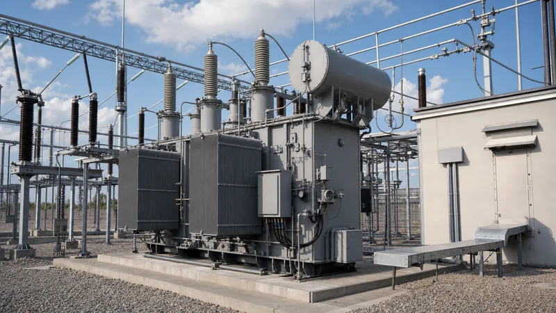
A station service transformer operates as an independent, highly dependable step-down electrical transformer that bridges substation medium-voltage (MV) or high-voltage (HV) busbars to the low-voltage auxiliary distribution network. Unlike primary power apparatus, the functional mandate of an SST is not to transmit bulk commercial power, but to preserve the operational autonomy and defence mechanisms of the substation itself.
The primary winding is commonly energised from the substation MV bus (such as 11 kV, 22 kV, or 33 kV), the delta-connected tertiary winding of a large power transformer, or directly from an incoming utility distribution feeder. The secondary winding delivers a standard three-phase, four-wire supply (400V phase-to-phase / 230V phase-to-neutral in IEC territories, or 480V / 277V in IEEE regions). High-reliability substations deploy two independent SSTs supplied from separate bus sections or feeders. These feed a split low-voltage AC switchboard equipped with a bus-tie circuit breaker and an Automatic Transfer Switch (ATS). If one station service transformer trips due to a primary feeder fault, the ATS transfers critical loads—such as direct current (DC) battery rectifiers, supervisory control and data acquisition (SCADA) processors, and fire suppression systems—within 100 to 500 milliseconds, preventing blackouts across control circuits as described in our guide on substation transformer design and siting.
Station Service Transformer vs Station Service Voltage Transformer
A standard station service transformer connects to medium-voltage networks, whereas a station service voltage transformer connects directly to high-voltage transmission lines up to 500 kV to extract station power in remote locations. Transmission-level substations often lack nearby distribution grids, making it economically prohibitive to run dozens of kilometres of MV power lines merely to supply a few hundred kilovolt-amperes (kVA) of station power.
An SSVT bridges this engineering gap by merging the design features of an inductive voltage transformer—detailed in our instrument transformers guide—with the thermal capacity and continuous current characteristics of a distribution power transformer. Housed within a single outdoor, oil-filled porcelain or composite insulator bushing, an SSVT taps high-voltage transmission lines (such as 138 kV, 230 kV, or 345 kV) and steps the voltage down directly to 120V, 240V, or 480V. The table below illustrates the critical technical distinctions between standard SST units and transmission-class SSVTs:
| Engineering Parameter | Standard Station Service Transformer (SST) | Station Service Voltage Transformer (SSVT) |
|---|---|---|
| Primary Voltage Range | 3.3 kV to 36 kV (MV bus or tertiary) | 46 kV to 550 kV (Transmission bus) |
| Secondary Voltage | 400V / 230V or 480V / 277V (3-phase) | 120V, 240V, or 480V (1-phase or 3-phase bank) |
| Standard Power Rating | 50 kVA to 2,500 kVA | 10 kVA to 333 kVA per single-phase unit |
| Insulation Medium | Mineral oil, synthetic ester, or cast resin | Oil-immersed or SF6 gas insulated |
| Basic Impulse Level (BIL) | 40 kV to 170 kV BIL | 250 kV to 1,675 kV BIL |
| Core and Coil Topology | Standard distribution core, three-phase | Shielded high-insulation inductive single-phase stack |
| Primary Application | Urban/industrial substations with MV access | Remote transmission switchyards, wind farms, solar plants |
Key Electrical Specifications and Engineering Standards
Engineering a station service transformer requires rigorous compliance with international consensus standards, specifically IEC 60076 for global contracts and IEEE C57.12.00 across North American projects. Specifying engineers must define exact dielectric, thermal, and short-circuit parameters to survive harsh outdoor switchyard environments.
Key engineering specifications include:
- Basic Lightning Impulse Insulation Level (BIL): Must match the substation insulation coordination study. For an 11 kV primary winding, IEC specifies a 75 kV BIL, while a 33 kV primary requires a 170 kV BIL. IEEE systems using 34.5 kV class transformers typically mandate 150 kV or 200 kV BIL.
- Short-Circuit Impedance (%Z): Standard SST impedance ranges between 4.0% and 6.0% under IEC 60076-5. An impedance below 4.0% yields excessive fault current that overstresses low-voltage switchgear breakers, whereas an impedance above 6.5% causes unacceptably high voltage drops during large induction motor starting (e.g., oil pumps and HVAC compressors).
- Vector Group and Grounding: The most prevalent configuration for three-phase units is Dyn11 (delta primary, wye secondary with neutral brought out, 30-degree phase lead). Dyn11 isolates third-harmonic currents from passing upstream into the MV bus and provides a stable neutral point for single-phase 230V auxiliary circuits.
- Temperature Rise and Dielectric Fluid: Standard mineral oil (Class A, 60/65°C average winding rise) or high-fire-point natural esters (K-class fluid, 65/85°C rise) for locations with strict environmental containment rules. Cast-resin dry-type units are favoured when the station service transformer sits inside an indoor switchgear room to eliminate fire hazards.
Coordination with upstream relay protection is critical. Implementing dedicated overcurrent and restricted earth fault schemes prevents auxiliary faults from tripping main grid circuits, as highlighted in our substation transformer protection engineering guide.
Step-by-Step Station Service Transformer Sizing Procedure
Sizing a station service transformer correctly ensures that nominal operating temperatures are maintained during peak continuous loads while accommodating high inrush currents from motor starting. Electrical engineers employ a five-step methodical calculation based on total connected load, coincidence factors, and allowable system voltage drop.
- Tabulate continuous and non-continuous auxiliary loads: Group all substation loads into continuous categories (battery charger float load, SCADA RTU systems, control building HVAC, building lighting) and non-continuous categories (tap changer drive motors, transformer oil cooling pumps, compressor motors, fire water pumps).
- Apply diversity and demand factors: Continuous loads generally operate with a demand factor of 1.0. Intermittent loads such as On-Load Tap Changer (OLTC) drive motors operate with a diversity factor between 0.15 and 0.30. Sum the diversified running volt-amperes ($P_{continuous} + P_{intermittent}$).
- Calculate the peak motor starting transient: Identify the largest single low-voltage induction motor (typically a 15 kW to 30 kW cooling fan bank or oil circulation pump). Determine its locked-rotor kVA ($kVA_{LR} \approx 6 \times kVA_{nominal}$).
- Evaluate transient voltage drop limits: Verify that the transformer size ($S_n$) maintains low-voltage bus voltage drop below 10% during across-the-line starting of the largest motor using the formula: $$\Delta V(\%) \approx \frac{kVA_{LR}}{S_n} \times \%Z \times \sin(\theta)$$ where $\%Z$ is transformer percent impedance and $\sin(\theta)$ is the starting power factor angle (typically 0.85 to 0.90).
- Incorporate future margin and select standard kVA rating: Add a mandatory 20% to 25% design margin for future substation expansion. Select the next standard manufacturing rating in accordance with IEC or IEEE tables (e.g., 100 kVA, 160 kVA, 250 kVA, 400 kVA, 630 kVA, 1000 kVA, or 1600 kVA).
Substation Auxiliary Power Architecture and Redundancy Schemes
A resilient auxiliary power system utilizes diverse incoming sources and robust switching logic to ensure substation reliability. If both main and backup auxiliary power fail, substation storage batteries deplete within 8 to 12 hours, resulting in a total loss of telemetry, tripping capability, and grid protection.
Modern utility engineering implements three primary architectural configurations:
- Two-Transformer Dual-Bus Architecture (Main/Standby): Two identical station service transformers, SST-1 and SST-2, are supplied from two physically isolated MV busbar sections. Under normal conditions, each SST feeds one section of a split LV switchboard with the bus-tie breaker open. If SST-1 fails, its incoming breaker opens and the bus-tie automatically closes, energising the entire board from SST-2.
- Tertiary-Winding SST with External Distribution Backup: The primary SST is connected directly to the delta tertiary winding of a 400/132 kV or 230/69 kV autotransformer. The backup SST is fed from an independent local rural distribution line. This guarantees auxiliary power even when the main transmission transformer is de-energised for overhaul.
- Diesel Generator or BESS Black-Start Integration: Critical strategic transmission substations pair a station service transformer with an emergency diesel generator or a lithium-iron phosphate battery energy storage system (BESS). The emergency generator starts automatically within 10 to 30 seconds if both SST incoming supplies drop below 80% nominal voltage.
Next steps: specifying and sourcing
Procuring a dependable station service transformer or SSVT requires clear engineering data sheets before soliciting quotations. When submitting a request for proposal (RFP), provide our design team with your exact primary voltage, secondary nominal voltage, required kVA capacity, environmental conditions (ambient temperature extremes, altitude, seismic zone), BIL insulation levels, and preference for oil-immersed transformers or dry-type transformers. For complete turnkey grid expansions or packaged secondary distribution needs, review our integrated compact substation solutions or request engineering review and commercial pricing directly through our transformer quotation portal.
Frequently asked questions
What is the primary function of a station service transformer?
The primary function of a station service transformer is stepping down transmission or medium-voltage bus power to low AC voltages, such as 400V or 480V. This powers substation auxiliary loads including circuit breaker mechanisms, protection relays, battery chargers, transformer cooling systems, and switchyard lighting.
What is the difference between an SST and an SSVT?
An SST connects to medium-voltage busbars or tertiary windings up to 36 kV and supplies 50 kVA to 2,500 kVA of three-phase power. An SSVT connects directly to high-voltage transmission lines up to 500 kV, stepping power down in capacities between 10 kVA and 333 kVA per phase.
Why are delta-wye (Dyn11) vector groups preferred for station service transformers?
A Dyn11 vector group traps third-harmonic zero-sequence currents inside the delta primary winding, preventing distortion from flowing back into the upstream grid. The grounded wye secondary provides a stable neutral conductor required to supply standard 230V single-phase substation auxiliary equipment.
What happens if a substation loses station service power?
If station service power is completely lost, the substation transitions to its emergency DC battery bank. These batteries support control relays and trip coils for 8 to 12 hours, after which all telemetry, communication, switchgear actuation, and transformer cooling systems fail, forcing a total switchyard shutdown.
What is the typical impedance value for a station service transformer?
Standard impedance for a station service transformer ranges between 4.0% and 6.0% under IEC 60076 and IEEE C57.12.00 standards. This balance limits low-voltage short-circuit fault currents within breaker ratings while preventing excessive voltage drop during the direct-on-line starting of large pump or fan motors.
Tags: station service transformer station service voltage transformer substation auxiliary power power transformers transformer sizing


