Key takeaways
- Replacing or retrofitting legacy substation transformers requires matching impedance within plus or minus 7.5 percent to maintain balanced load-sharing across existing parallel banks under IEEE C57.12.00 Clause 5.10.
- Capitalised loss evaluation formulas (Total Owning Cost) balance initial capital expenditure with core (no-load) and winding (load) losses calculated over a typical 30-year operational life cycle.
- Legacy utility transformers often utilise proprietary tank dimensions, requiring custom throat transitions and bus duct matching when installing modern substation replacements.
- Dielectric acceptance for 110 kV class transformer retrofits demands lightning impulse withstand levels (BIL) verified up to 550 kV in accordance with IEEE C57.12.90 Clause 10.
- Condition assessment through dissolved gas analysis (DGA) and degree of polymerisation testing governs whether life-extension refurbishment or full unit replacement is technically justified.
Quick answer: Engineering specifications for legacy transformers and their equivalent modern replacements require rigorous alignment with IEEE C57.12 or IEC 60076 standards. Successful specification depends on matching rated power (kVA/MVA), short-circuit impedance tolerance (within ±7.5%), high-voltage insulation BIL, thermal class, and terminal geometry to guarantee seamless operation in utility or industrial networks.
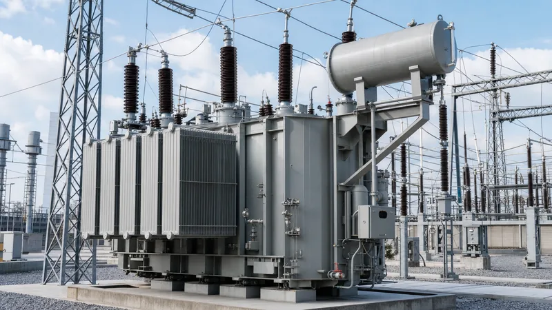
Across utility grids, heavy industrial plants, and renewable energy substations, engineers frequently encounter installed fleets of legacy transformers that have reached or exceeded their nominal 30-to-40-year operational lifespan. Procuring modern drop-in replacements or specifying compatible new equipment requires a deep understanding of core construction, winding metallurgy, and thermal dissipation metrics. Whether evaluating existing vintage transformers or drafting an engineering procurement specification for modern equivalents, engineers must balance initial capital expenditure against long-term operational efficiency.
Modern power distribution projects demand precise compatibility with legacy grid infrastructure while integrating advanced diagnostic instrumentation. Navigating the replacement of legacy utility transformers involves auditing original nameplate ratings, thermal class boundaries, on-load tap changer schemes, and structural footprint limitations to ensure complete compatibility without disruptive civil redesign.
Technical Architecture and Standards for Legacy Transformers
Engineering standards for utility-grade transformers diverge between North American IEEE/ANSI frameworks and international IEC frameworks, dictating fundamental insulation levels, temperature rise thresholds, and core loss calculations. Legacy transformers deployed throughout North America adhere primarily to IEEE C57.12.00, whereas international installations comply with IEC 60076-1.
A critical divergence lies in standard temperature rise ratings. Under IEEE C57.12.00 Clause 5.11, liquid-immersed transformers are rated for a 65°C average winding rise above a 30°C average ambient (with a maximum ambient of 40°C), permitting an ultimate hot-spot temperature of 110°C using thermally upgraded kraft paper. Conversely, IEC 60076-2 specifies a standard 65 K average winding temperature rise above ambient, but calculates thermal margins against a 98°C hot spot for standard non-upgraded cellulose insulation.
Short-circuit withstand capabilities are another governing parameter. According to IEEE C57.12.00 Table 10, transformers must withstand mechanical and thermal effects of external short circuits without damage for a minimum duration of 2.0 seconds. When engineering drop-in replacements for legacy transformers, engineers must confirm that the mechanical clamping structure maintains core tightness under asymmetrical peak forces, which can exceed 25 times nominal full-load current.
Designers must also audit primary terminal arrangements. High-voltage connections frequently involve draw-lead or bottom-connected porcelain or composite bushings compliant with IEEE C57.19.00, while low-voltage terminations often feature full-height air terminal chambers or segmented throat connections configured for non-segregated phase bus duct interfaces.
Total Owning Cost Calculation: Evaluating Core and Load Losses
Capitalised loss evaluation determines the true lifetime cost of operating utility transformers by penalising no-load and load losses using financial evaluation coefficients specified in utility tenders. Purchasing decisions based solely on purchase price frequently result in suboptimal asset utilisation over a 30-year operational window.
The Total Owning Cost (TOC) formula established under IEEE C57.120 evaluates the lifetime cost as follows:
TOC = Purchase Price + (A × P_nl) + (B × P_ll)
Where:
- A is the capitalisation factor for no-load loss (USD or GBP per kilowatt, reflecting continuous 24/7 core excitation).
- B is the capitalisation factor for load loss (USD or GBP per kilowatt, factoring in duty cycle, loading factor, and peak demand charges).
- P_nl is the guaranteed no-load loss (core loss) in kW at rated voltage and frequency.
- P_ll is the guaranteed load loss (winding and stray loss) in kW at rated current and reference temperature (75°C or 85°C).
Consider a practical comparison for a 25 MVA, 115 kV to 13.8 kV substation transformer operating on an industrial network. The client specifies loss valuation factors of A = $8,500/kW and B = $2,200/kW. Modern core designs employing high-permeability grain-oriented (HGO) silicon steel dramatically reduce no-load excitation losses compared to legacy mid-century silicon steels.
Suppose Option 1 (a standard core build) delivers P_nl = 14.5 kW and P_ll = 82.0 kW at a purchase price of $480,000. Option 2 (a low-loss step-lap core design) delivers P_nl = 10.2 kW and P_ll = 74.0 kW at a purchase price of $525,000.
Applying the TOC evaluation:
- Option 1 TOC = $480,000 + ($8,500 × 14.5) + ($2,200 × 82.0) = $480,000 + $123,250 + $180,400 = $783,650.
- Option 2 TOC = $525,000 + ($8,500 × 10.2) + ($2,200 × 74.0) = $525,000 + $86,700 + $162,800 = $774,500.
Although Option 2 requires $45,000 more initial capital, it yields an overall net saving of $9,150 over the evaluated life cycle, demonstrating that high-efficiency engineering provides superior lifetime economics when operating vintage transformers or modern equivalents.
Specification Comparison: Legacy Configurations vs Modern Equivalents
When specifying new equipment or replacing legacy units in the field, engineers must verify electrical parameters against modern manufacturing standards. The following engineering comparison illustrates key design differences between vintage mid-to-late 20th-century utility transformers and modern precision-manufactured equivalents built to current international specifications.
| Engineering Parameter | Legacy Mid-Century Specifications | Modern High-Performance Equivalents | Reference Standard |
|---|---|---|---|
| Core Metallurgy & Construction | Non-step-lap conventional cold-rolled grain-oriented steel | Laser-scribed, high-permeability step-lap mitered core | IEC 60076-1 / IEEE C57.12.00 |
| Winding Insulation System | Standard uninhibited kraft paper, 55°C rise limit | Thermally upgraded paper or synthetic aramid, 65°C/75°C rise | IEEE C57.100 / IEC 60076-14 |
| Dielectric Fluid Medium | Uninhibited mineral oil (early units may contain PCB traces) | Inhibited naphthenic mineral oil or synthetic/natural ester | ASTM D3487 / IEC 60296 |
| Impedance Tolerance (%Z) | ±10% allowable factory tolerance | ±7.5% standard tolerance (tighter on request) | IEEE C57.12.00 Clause 5.10 |
| Cooling Configuration | OA / FA (natural oil, forced air) | ONAN / ONAF / ODAF automated stages | IEC 60076-3 Clause 4 |
| Gasket & Sealing Technology | Cork-neoprene composite gaskets, welded tank covers | Fluoroelastomer / fluorosilicone O-rings, bolted machined flanges | IEEE C57.12.10 |
| Condition Monitoring | Basic dial thermometer, magnetic liquid level gauge | Online multi-gas DGA, optical fibre hot-spot sensors | IEEE C57.143 / IEC 60840 |
To examine cooling design principles and thermal rating stages in greater detail, consult our technical guide on ONAF transformer cooling and thermal performance. Proper thermal planning prevents accelerated degradation of the solid dielectric insulation.
Step-by-Step Engineering Procedure for Replacing Legacy Transformers
Retrofitting or replacing legacy transformers in existing utility substations requires a systematic assessment of civil, electrical, and control interfaces to avoid site modification delays.
- Audit legacy nameplate and historical test logs: Record base rated power (MVA), primary and secondary voltages, vector group (e.g., Dyn1 or YNd11), basic impulse level (BIL), and exact percentage impedance (%Z) at the reference base. Review dissolved gas analysis (DGA) records and historical load profiles to identify system duty cycles.
- Perform 3D laser spatial scanning of the civil pad: Survey existing containment bunds, blast wall clearances, foundation pier centre-lines, and overhead line drop zones. Verify that foundation load-bearing limits accommodate modern unit total weights, which may vary due to modern acoustic and core shielding requirements.
- Specify terminal alignment and throat dimensions: Measure height, phase-to-phase spacing, and center-line offset of existing high-voltage and low-voltage bushings or cable boxes. When interfacing with existing switchgear, match bus duct flange bolt patterns directly to the replacement unit's terminal enclosure.
- Determine protection and tap-changing compatibility: Align control wiring schemas for current transformers (CTs) mounted inside bushing turrets. Review the existing load tap changer design and controls to ensure the replacement tap-changer controller communicates seamlessly with supervisory control and data acquisition (SCADA) systems via IEC 61850, Modbus, or DNP3 protocols.
- Confirm protection scheme compatibility: Ensure neutral grounding arrangements and differential protection zones match existing substation relays. Review overall protection strategies in our substation transformer protection engineering guide to coordinate overcurrent, differential, and restricted earth fault schemes.
- Execute factory acceptance testing (FAT): Witness dielectric and thermal routine tests at the manufacturing plant before dispatch, ensuring complete compliance with client specifications and IEEE C57.12.90 requirements.
Substation Retrofit and Fleet Replacement Checklist
Engineers drafting procurement specifications to replace aged legacy transformers should paste the following engineering requirements directly into their Request for Proposal (RFP) technical schedules.
Ensure that all parameters below are explicitly defined to prevent mismatched replacements:
- Operating Environment: Ambient temperature range (-25°C to +45°C), seismic zone qualification (IEEE 693 High Seismic Performance Level), altitude (≤1000 m standard; derating applied per IEEE C57.12.00 Clause 5.4 if above 1000 m).
- Electrical Ratings: Rated MVA (e.g., 15/20/25 MVA ONAN/ONAF/ONAF), primary nominal voltage (e.g., 69 kV Delta, 350 kV BIL), secondary voltage (e.g., 13.8 kV Wye grounded, 110 kV BIL).
- Short-Circuit Impedance: Target %Z at self-cooled base rating (e.g., 8.0% ± 7.5% tolerance) to permit parallel operation with surviving substation units without circular circulating currents.
- Tap Changer Requirements: De-energised tap changer (DETC) on HV side (±2 × 2.5%) or On-Load Tap Changer (OLTC) with vacuum interrupters, 33 positions, motor drive unit, and digital paralleling relay.
- Sound Level Limits: Maximum allowable decibel levels measured according to NEMA TR-1 / IEEE C57.12.90, typically 65 to 72 dBA at 100% forced cooling.
- Diagnostics and Accessories: Magnetic oil level gauge with microswitches, pressure relief device (PRD) with directional deflector, rapid pressure rise relay (standard mechanical rate-of-rise type), multi-stage winding temperature indicators (WTI), and optical fibre temperature probes embedded directly into the winding hot spots.
- Fluid Containment and Valving: Stainless steel sampling valves at top and bottom of tank, drain valve with sampling port, and nitrogen blanket or rubber membrane conservator preservation system.
For high-capacity installations connecting directly to national grids, cross-reference design provisions against our transmission transformer engineering guide.
Factory Acceptance Testing and Commissioning Standards
Factory acceptance testing (FAT) for transformers replacing legacy utility transformers validates electrical clearances, dielectric integrity, and thermal ratings prior to freight and rigging. All testing procedures must strictly adhere to IEEE C57.12.90 or IEC 60076-3.
Mandatory routine tests conducted on every unit include:
- Winding Resistance Measurement: Conducted across all taps using a four-wire Kelvin digital low-resistance ohmmeter (DLRO) to detect loose internal joints or winding abnormalities (IEEE C57.12.90 Clause 5).
- Voltage Ratio and Phase Displacement: Verified with a three-phase transformer turns ratio (TTR) set across all tap positions. Tolerance must not exceed ±0.5% of nameplate ratio (IEEE C57.12.00 Clause 9.1).
- Insulation Resistance and Power Factor / Dissipation Factor: Core-to-ground, primary-to-secondary, and winding-to-ground insulation tested at 2.5 kV or 5 kV DC; 10 kV AC power factor dissipation test should indicate a loss tangent (tan δ) below 0.5% at 20°C.
- Applied and Induced Overvoltage Tests: Separate-source AC voltage withstand test combined with induced partial discharge testing (PD ≤ 100 pC at 1.58 Um / √3) to confirm void-free vacuum impregnation.
- Lightning Impulse Withstand: Full wave and chopped wave impulse tests applied to line terminals to verify insulation against high-voltage atmospheric surges.
Detailed verification methods and acceptance thresholds are covered comprehensively in our engineering overview on power transformer testing protocols.
Next steps: specifying and sourcing
When specifying custom-engineered units to retrofit or replace installed legacy transformers, submitting precise parameters ensures rapid turnaround and exact engineering compatibility. Please provide your single-line diagram (SLD), site layout drawings, primary and secondary voltages, winding vector group, basic impulse level (BIL), and impedance tolerances.
Explore our engineering capabilities across high-voltage power transformers, outdoor oil-immersed distribution transformers, and integrated prefabricated transformer substations. For dedicated tender proposals, custom dimension matching, and competitive pricing schedules, submit your technical schedule directly via our transformer quote page or get in touch with our technical sales engineers through the contact page.
Frequently asked questions
Can a modern transformer operate in parallel with legacy substation transformers?
Yes, provided the primary and secondary voltages, vector group, and phase angles match exactly. Furthermore, the percentage impedance (%Z) of the new unit must match the existing transformer within ±7.5% under IEEE C57.12.00 Clause 5.10 to prevent uneven load sharing and dangerous circulating currents.
What information is required to replace a legacy substation transformer?
Provide the original nameplate data, including rated kVA/MVA, HV/LV voltages, connection symbol (vector group), %Z impedance, basic impulse insulation level (BIL), and total weight. Dimensional drawings showing bushing centre-lines, terminal heights, and foundation anchor points are also vital to ensure a drop-in physical fit.
How does Total Owning Cost affect the evaluation of utility transformers?
Total Owning Cost (TOC) combines purchase price with capitalised no-load and load loss penalties evaluated over the transformer's 30-year operational life. Specifying low-loss core steel may increase initial capital expense but saves significant operational expenditure over the asset life cycle.
What is the typical lifespan of oil-immersed utility transformers?
With regular oil maintenance and operation within rated thermal limits (65°C winding rise), oil-immersed transformers typically achieve a service life of 30 to 40 years. Degree of polymerisation (DP) testing of solid cellulose insulation below 200 indicates end-of-life status requiring decommissioning.
Are ester fluids compatible as drop-in dielectric liquids for transformer retrofits?
Synthetic and natural ester fluids can replace conventional mineral oil in retrofits, offering high fire points (>300°C) and biodegradability. However, the internal insulation structure, clearances, and gaskets must be reviewed by the manufacturer because ester fluids have higher viscosity and different dielectric permittivity.
Tags: substation transformers utility transformers legacy transformers power transformers substation engineering


