Key takeaways
- Procuring a Georgia transformer requires strict verification against IEEE C57.12.00 standards for temperature rise, dielectric withstand, and short-circuit impedance.
- A standard utility-scale transformer plant must maintain controlled winding cleanrooms with relative humidity below 40% to prevent moisture ingress into cellulose insulation.
- Factory acceptance testing for any ga transformer installation mandates sweep frequency response analysis and partial discharge limits below 100 pC at 1.5 times nominal line-to-ground voltage.
- Core loss evaluation formulas penalise inefficient designs by assessing capitalised no-load losses at rates frequently exceeding 4,000 USD per kilowatt over a 30-year lifecycle.
- Validating core clamping pressure between 1.0 and 1.5 MPa prevents core lamination displacement and excessive audible noise during energisation.
Quick answer: Sourcing a heavy-duty georgia transformer requires balancing strict North American IEEE/ANSI design standards, factory production audits, and comprehensive loss evaluation formulas. Modern industrial and utility buyers evaluate regional manufacturing capabilities against core loss guarantees, insulation moisture levels below 0.5%, and short-circuit withstand integrity before issuing purchase orders.
Procuring heavy power apparatus across North America involves rigorous technical vetting of every regional supplier and manufacturing facility. When electrical utilities, EPC contractors, and industrial plants evaluate proposals from a regional transformer corporation or domestic assembly hub, technical criteria must dictate the commercial selection. Sourcing high-voltage liquid-immersed units requires deep scrutiny of winding methodologies, tank fabrication standards, core steel grades, and testing facilities to guarantee 30 to 40 years of continuous service under dynamic network loading.
Technical Standards for a Georgia Transformer in Grid Applications
A utility-grade Georgia transformer must comply with North American IEEE C57 standards governing thermal boundaries, insulation coordination, and mechanical short-circuit strength. In transmission and distribution systems operating between 13.8 kV and 500 kV, design engineers reference IEEE C57.12.00 Table 5 for dielectric test levels and IEEE C57.12.90 for standard testing procedures.
Thermal ratings dictate that average winding temperature rise must not exceed 65 °C above a 30 °C average ambient temperature, with a maximum hottest-spot temperature rise limited to 80 °C under full continuous nameplate rating. Meeting these thresholds requires dynamic oil flow optimisation inside the tank, whether configured for mineral oil (inhibited or uninhibited per ASTM D3487) or natural ester fluids complying with ASTM D6871. Understanding basic magnetic core configurations, as detailed in our 3 Phase Transformer Guide, helps specification engineers establish appropriate flux density ceilings, typically between 1.65 and 1.72 Tesla, preventing core saturation during temporary overvoltage transients.
Evaluating a High-Voltage Transformer Plant and Manufacturing Facility
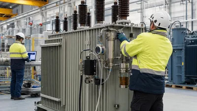
Auditing a modern transformer plant requires direct inspection of the core stacking line, winding cleanrooms, vapour-phase drying chambers, and high-voltage test bays. Production quality cannot be retrofitted during final assembly; it depends entirely on process controls enforced on the factory floor.
During an on-site audit of a transformer manufacturing facility, engineering inspectors verify several critical production stations:
- Core cutting and assembly: Robotic slitting and step-lap stacking of grain-oriented electrical steel (e.g., 23ZH090 or equivalent laser-treated grades) minimise no-load excitation currents and core vibrations.
- Winding cleanroom environment: Winding areas for disc and helical coils must maintain positive atmospheric pressure, active dust filtration, and relative humidity strictly below 40% to prevent hygroscopic Kraft paper insulation from absorbing moisture.
- Vapour-phase drying (VPD): The assembled core-and-coil assembly must undergo solvent vapour-phase drying until residual moisture in solid insulation drops below 0.5% by weight.
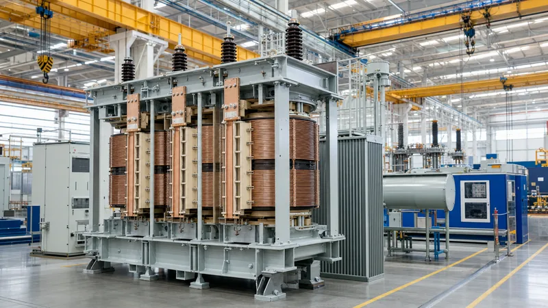
- Clamping and tanking: Mechanical clamping structures must deliver uniform axial compression between 1.0 and 1.5 MPa across all phase coils to withstand electromagnetic forces during external through-faults.
For large power units incorporating on-load tap changers, the mounting and drive shaft alignment demand exceptional accuracy, following the design principles highlighted in our Load Tap Changer Guide.
Loss Capitalisation: Engineering Calculation for GA Transformer Tenders
Total owning cost evaluations for a ga transformer tender determine commercial viability by adding capitalised lifecycle loss penalties to the initial purchase price. Utility procurement teams penalise inefficient units using Total Owning Cost (TOC) equations where no-load core losses and load losses carry heavy dollar multipliers.
The standard industry TOC equation is formulated as:
TOC = Purchase Price + (A × P0) + (B × Pk)
Where:
- P0: Guaranteed no-load loss at rated voltage and 20 °C (kW).
- Pk: Guaranteed load loss at base rating and reference temperature (kW).
- A: Capitalised cost of no-load loss ($/kW), typically $4,000 to $9,000/kW depending on energy rates and asset life.
- B: Capitalised cost of load loss ($/kW), typically $1,500 to $3,500/kW based on expected loading factors.
Consider a practical bid comparison for a 40 MVA, 115 kV to 13.8 kV substation transformer with evaluation factors A = $5,500/kW and B = $2,200/kW:
- Bidder A: Initial Price = $1,150,000; No-load loss (P0) = 18.5 kW; Load loss (Pk) = 112 kW.
TOC = $1,150,000 + ($5,500 × 18.5) + ($2,200 × 112) = $1,150,000 + $101,750 + $246,400 = $1,498,150. - Bidder B: Initial Price = $1,080,000; No-load loss (P0) = 24.0 kW; Load loss (Pk) = 135 kW.
TOC = $1,080,000 + ($5,500 × 24.0) + ($2,200 × 135) = $1,080,000 + $132,000 + $297,000 = $1,509,000.
Although Bidder A has a $70,000 higher sticker price, Bidder A delivers lower total lifecycle ownership costs by saving $10,850 in capitalised losses over 30 years.
Core and Winding Design Criteria for Georgia Transformer Corporation Specifications
Specifying core geometry and winding topology for heavy industrial apparatus requires reconciling electrical clearance requirements with transportation envelopes and mechanical robustness. A procurement package framed for a domestic enterprise or a regional georgia transformer corporation must define coil construction methods explicitly.
Continuous disc windings with radial oil cooling ducts are mandatory for voltages above 69 kV to maintain uniform impulse voltage distribution across insulation layers. Copper conductors should feature thermally upgraded Kraft paper or continuously transposed conductors (CTC) to reduce eddy current losses. The table below outlines standard design criteria across distinct voltage classes:
| Nominal System Voltage (kV) | Basic Impulse Level BIL (kV peak) | Winding Style | Impedance Tolerance (%Z) | Maximum Sound Level (dBA at ONAN) |
|---|---|---|---|---|
| 13.8 / 24.94 | 95 / 150 | Circular Layer / Disc | ±7.5% per IEEE C57.12.00 | 58 - 62 |
| 34.5 / 46 | 200 / 250 | Continuous Disc | ±7.5% per IEEE C57.12.00 | 63 - 67 |
| 69 / 115 | 350 / 550 | Interleaved Disc / CTC | ±7.5% per IEEE C57.12.00 | 68 - 73 |
| 230 | 850 / 950 | Shielded Disc / CTC | ±5.0% per IEEE C57.12.00 | 74 - 78 |
Maintaining these mechanical tolerances ensures that when units are subjected to downstream short circuits, the physical displacement of windings remains virtually zero, preserving dielectric oil clearances.
Factory Acceptance Testing Protocols for GA Transformer Deliveries
Factory acceptance testing (FAT) for any heavy liquid-filled unit verifies structural integrity, dielectric insulation margins, and thermal performance prior to transport. Standard testing schedules follow IEEE C57.12.90 and IEC 60076-1 guidelines, separating procedures into routine, design, and special tests.
A rigorous FAT sequence follows these sequential steps:
- Winding resistance measurement: Performed on all taps using a precision digital micro-ohmmeter to establish reference baselines for temperature rise calculations.
- Voltage ratio and vector group verification: Confirms turns ratios across every tap position within the allowable tolerance of 0.5% specified in IEEE C57.12.00 clause 9.1.
- Insulation resistance and dissipation factor: Polarization Index (PI) must exceed 2.0, and winding power factor (tan delta) must remain below 0.5% at 20 °C.
- Dielectric withstand testing: Applied voltage and induced voltage tests with simultaneous partial discharge monitoring. Apparent partial discharge charge must remain below 100 pC at 1.5 times maximum system operating voltage.
- Lightning impulse testing: Full-wave and chopped-wave impulses applied to high-voltage terminals to confirm BIL ratings without insulation puncture.
- Sweep Frequency Response Analysis (SFRA): Performed before and after factory testing to produce fingerprint transfer functions per IEEE C57.149 for later comparison on site.
Comprehensive FAT methodologies mirror the detailed field criteria documented in our Power Transformer Testing Guide, guaranteeing that units depart the factory free of latent dielectric anomalies.
Transport, Site Rigging, and Commissioning Considerations
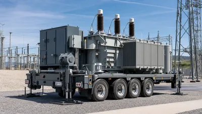
Transporting heavy transformers from an assembly plant to utility substations presents severe logistical and mechanical risks that require multi-axis impact monitoring. Units rated above 20 MVA are stripped of radiators, bushings, and conservator tanks, then transported under dry nitrogen or dry synthetic air holding positive pressure between 14 and 35 kPa.
Three-axis digital impact recorders mounted directly to the transformer tank monitor transit conditions. Any shock acceleration exceeding 3.0 g in the longitudinal or lateral axis, or 2.0 g in the vertical axis, triggers mandatory internal inspection and non-destructive re-testing, including SFRA and core ground resistance checks. Once rigged onto the concrete pad, vacuum filling with degassed, dehydrated dielectric oil must commence under a vacuum level below 130 Pa (1 Torr) to eliminate air voids within solid cellulose insulation. Long-term operating life can subsequently be preserved through regular oil screening and condition monitoring detailed in our Transformer Maintenance Guide.
Next steps: specifying and sourcing
Procuring a dependable power transformer requires an unambiguous technical specification package. When preparing your RFQ for a regional project, ensure your engineering team provides full network details: rated power (ONAN/ONAF/OFAF), primary and secondary voltages, winding connection symbols, required BIL levels, tap changer arrangements, and site environmental boundaries. If loss evaluation formulas apply, supply capitalised loss factors upfront to allow design teams to optimise magnetic core and copper conductor configurations. Explore our range of high-performance power transformers, industrial oil-immersed transformers, and engineered transformer substations, or visit our transformer quotation page to discuss technical schedules directly with our application engineering team.
Frequently asked questions
What core standards govern a Georgia transformer installation?
A Georgia transformer installation is primarily governed by IEEE C57.12.00 for general requirements, IEEE C57.12.90 for test codes, and NFPA 70 (National Electrical Code) for structural installation clearances. Medium and high-voltage transmission units also follow NERC reliability standards and IEEE C57.91 thermal loading guides.
How do engineers evaluate total owning cost for a ga transformer?
Engineers evaluate total owning cost by adding capitalised lifecycle loss penalties to the baseline purchase price. The calculation combines the manufacturer's guaranteed no-load core losses and winding load losses multiplied by predetermined utility dollar-per-kilowatt rates over an operational window of 25 to 35 years.
What is the acceptable partial discharge limit during factory testing?
During factory induced-voltage testing per IEEE C57.12.90, the continuous partial discharge level must remain below 100 to 250 picocoulombs (pC) when energised at 1.5 times the nominal line-to-ground operating voltage, confirming void-free insulation.
Why are impact recorders used when shipping from a transformer plant?
Digital three-axis impact recorders verify that internal core-and-coil assemblies have not experienced shock forces exceeding 2.0 to 3.0 g during rail or heavy-haul transport. Excessive shocks can loosen mechanical clamping structures, shear internal leads, or shift core laminations.
What moisture level is required in transformer solid insulation before oil filling?
The solid cellulose Kraft paper insulation must maintain a moisture content below 0.5% by dry weight following factory vapour-phase drying. Keeping moisture below this limit ensures maximum dielectric strength and decelerates thermal ageing of the paper insulation matrix.
Tags: georgia transformer georgia transformer corporation ga transformer transformer plant power transformer