Key takeaways
- A standard European transformer operates at 50 Hz with a primary distribution voltage of 11 kV, 20 kV, or 33 kV and a secondary low-voltage output of 400 V phase-to-phase and 230 V phase-to-neutral.
- Commission Regulation (EU) 2019/1783 (EcoDesign Tier 2) enforces strict maximum no-load and load loss limits for liquid-immersed and dry-type transformers installed across Europe.
- Operating a North American 60 Hz transformer on a 50 Hz European grid increases core magnetic flux density by 20%, demanding a proportional primary voltage reduction or a 20% kVA capacity derating.
- The standard secondary winding connection across European networks is Dyn11, which suppresses third-harmonic currents and provides a neutral point for single-phase 230 V loads.
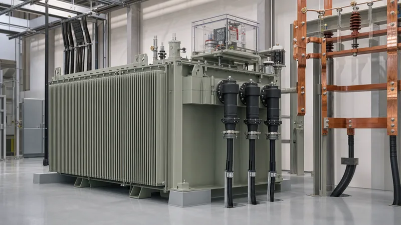
- Hermetically sealed liquid-immersed European units utilise integrated multifunction protection devices monitoring gas accumulation, overpressure, and dual-level oil temperature.
Quick answer: A European transformer is a distribution or power transformer engineered to European electrical grid parameters, typically stepping medium voltage down to 400 V three-phase / 230 V single-phase at 50 Hz. It must strictly comply with IEC 60076 series standards and EU EcoDesign Directive Tier 2 maximum loss thresholds (EN 50588-1).
Industrial operators, EPC contractors, and multinational manufacturing facilities regularly procure equipment intended for European facilities or export machinery across borders. Specifying or operating a European transformer involves navigating fundamental differences between European Committee for Electrotechnical Standardization (CENELEC) standards and North American IEEE/ANSI practices. These differences span operating frequency, core loss caps, winding configurations, and short-circuit withstand tolerances.
Engineering mistakes during specification lead to core saturation, excessive eddy current losses, nuisance protection tripping, or outright non-compliance with regional grid connection codes. This guide examines standard electrical ratings, mandatory efficiency thresholds, conversion dynamics for a us to eu transformer interface, and field-proven protection philosophies.
What Defines a European Transformer: Voltage, Frequency, and Vector Groups
A European transformer operates on a 50 Hz system frequency with secondary voltages standardised under IEC 60038 at 400 V line-to-line and 230 V line-to-neutral. Unlike North American split-phase 120/240 V or 480Y/277 V systems, the standard European distribution network delivers three-phase, four-wire power directly to consumer and industrial switchboards from a single distribution transformer.
Primary distribution voltages across European utilities typically include 10 kV, 11 kV, 15 kV, 20 kV, 22 kV, and 33 kV, depending on the national grid operator. Winding arrangements are virtually universal: the high-voltage (HV) winding connects in delta (D), while the low-voltage (LV) winding connects in star with an accessible neutral point (y or yn). The standard vector group is Dyn11, indicating an LV phase displacement that lags the HV by 30 degrees (11 o'clock position). This delta connection traps zero-sequence harmonic currents, mitigating third-harmonic distortion from non-linear plant loads, while the earthed neutral provides a dependable return path for 230 V single-phase branch circuits.
For facilities managing medium-voltage switchboards, detailed interface rules can be reviewed in our transformer protection engineering guide. European standards specify impedance voltage (%Z or $U_k$) at standardised tiers under EN 50588-1: typically 4% for ratings up to 630 kVA, and 6% for ratings from 800 kVA to 2500 kVA, balancing fault-current limitation against voltage regulation during motor starts.
EU EcoDesign Directive and EN 50588-1 Loss Standards
The EU EcoDesign Directive mandates legal maximum limits for transformer no-load losses ($P_o$) and load losses ($P_k$) via Regulation (EU) No 548/2014 and its amendment (EU) 2019/1783, known as Tier 2. Transformers entering service in the European Union that fail these efficiency thresholds cannot legally receive the CE mark or clear customs.
Standard EN 50588-1 defines the baseline maximum loss values for medium-voltage liquid-immersed transformers (rated up to 24 kV primary). Meeting Tier 2 thresholds requires manufacturers to deploy laser-scribed, high-permeability grain-oriented silicon steel (CRGO) or amorphous ribbon for cores, alongside high-conductivity electrolytic copper conductors with optimised transposition.
| Rated Power (kVA) | Tier 2 Max No-Load Loss $P_o$ (W) | Tier 2 Max Load Loss $P_k$ at 75°C (W) | Short-Circuit Impedance $U_k$ (%) |
|---|---|---|---|
| 250 | 300 | 2350 | 4.0 |
| 400 | 430 | 3250 | 4.0 |
| 630 | 600 | 4600 | 4.0 |
| 800 | 650 | 6000 | 6.0 |
| 1000 | 770 | 7600 | 6.0 |
| 1250 | 950 | 9500 | 6.0 |
| 1600 | 1200 | 12000 | 6.0 |
| 2000 | 1450 | 15000 | 6.0 |
| 2500 | 1750 | 18500 | 6.0 |
Dry-type transformers operate under separate loss categories within EN 50588-1 Table 2, which allow slightly higher absolute losses due to air-convection cooling constraints while maintaining strict energy-efficiency benchmarks. Verifying these losses requires calibrated precision power analysers during factory acceptance testing per IEC 60076-1 clause 10.
Engineering a US to EU Transformer Conversion System
An industrial facility using a us to eu transformer system must account for the fundamental magnetic and thermal effects of shifting between 60 Hz and 50 Hz power networks. When connecting North American 60 Hz machinery to a 50 Hz European utility, or installing imported 50 Hz machinery in a 60 Hz US plant, a basic step-up or step-down ratio is insufficient.
Core magnetic flux density ($B$) is governed by the transformer EMF equation:
$$B_{max} = \frac{V}{4.44 \cdot f \cdot N \cdot A_c}$$
Where $V$ is applied voltage, $f$ is network frequency in Hertz, $N$ is turn count, and $A_c$ is core cross-sectional area. Because magnetic flux is inversely proportional to frequency ($B \propto V/f$), connecting a standard 60 Hz transformer directly to a 50 Hz supply at its rated voltage increases peak magnetic flux density by a factor of $60 / 50 = 1.20$, representing a 20% increase.
Worked Engineering Calculation:
Consider a standard North American dry-type unit designed for 480 V at 60 Hz with an operating core flux density of 1.65 Tesla (T). The saturation threshold of standard CRGO steel is approximately 1.75 to 1.80 T.
- Calculate flux at 50 Hz: At rated 480 V and 50 Hz, operating flux density becomes $1.65 \times (60 / 50) = 1.98\text{ T}$. This drives the magnetic core deep into saturation.
- Resulting excitation current: Magnetising current escalates by 300% to 500%, drawing massive reactive power from the grid and triggering high audible noise (>80 dBA).
- Thermal impact: Core eddy-current and hysteresis losses cause rapid core overheating, violating temperature rise limits defined in IEC 60076-2.
- Engineered mitigation: To maintain safe flux density (1.65 T) at 50 Hz, input voltage must be reduced proportionally: $V_{50} = 480 \times (50 / 60) = 400\text{ V}$. Alternatively, the factory must wind the us to eu transformer with 20% additional core steel mass and a revised primary turns ratio.
- Capacity derating: When a 60 Hz design is fed at 50 Hz with reduced voltage, throughput kVA decreases by 16.7% ($1 - 50/60$) due to reduced thermal dissipation from internal fans and lower convective air velocity.
For projects requiring complex substation conversion schemes, examine our power transformer testing procedures to ensure dielectric and temperature-rise limits remain intact under off-frequency operation.
European Transformer Protection and Safety Schemes
Protection philosophies for a European transformer differ significantly from standard North American practice, which relies heavily on primary fuses and sudden-pressure relays on nitrogen-blanketed tanks. In Europe, distribution transformers are predominantly hermetically sealed liquid-immersed units without conservator tanks, or dry-type cast-resin units installed within indoor substations.
For hermetically sealed oil-filled designs, the primary safety component is an integrated multifunction safety detector, compliant with EN 50216-3. This instrument combines four critical monitoring functions into a single head mounted directly on the tank cover:
- Gas accumulation: Traps free gas bubbles generated by partial discharge, turn-to-turn insulation degradation, or oil overheating, actuating a float contact for early warning.
- Overpressure relief: Detects internal hydraulic shockwaves caused by internal short-circuit arcing, tripping the upstream MV vacuum breaker within milliseconds to prevent tank rupture.
- Two-stage temperature monitoring: Utilises dual dial thermistors for alarm (typically set at 85°C) and trip (typically set at 95°C) oil temperatures. For critical monitoring setups, review our guide on winding temperature guide and thermal limits.
- Fluid level: Monitors dielectric fluid volume to prevent energisation when bushings or core assemblies are exposed to air.
For substations deploying conservator-type power transformers, Buchholz relays per EN 50216-2 remain mandatory between the main tank and conservator pipework. Fire suppression engineering must align with local fire protection ordinances; detailed containment and suppression layouts can be referenced in our transformer fire protection system guide.
Factory Testing and Acceptance under CENELEC and IEC Standards
Factory acceptance testing (FAT) for any European transformer must follow the prescriptive verification procedures outlined in IEC 60076-1 through IEC 60076-5. Routine tests are mandatory for every serial production unit prior to dispatch from the factory floor.
The test protocol begins with winding resistance measurement (IEC 60076-1 clause 10.2) on all taps, using high-precision digital micro-ohmmeters to confirm balanced phase resistances and verify lack of inter-turn bridging. Voltage ratio and phase displacement verification follows (clause 10.3), checking turns accuracy within the ±0.5% tolerance band and proving the Dyn11 vector alignment.
Short-circuit impedance ($U_k$) and load loss ($P_k$) measurements are executed at rated frequency using a sinusoidal supply with total harmonic distortion (THD) below 3%, corrected to the reference temperature of 75°C for liquid-immersed units (or 120°C for class F dry-type units). Dielectric validation includes separate-source AC withstand testing and short-duration induced AC overvoltage testing (IEC 60076-3 clause 11) at twice rated secondary voltage for 60 seconds at elevated frequency (typically 150 Hz or 200 Hz) to avoid core saturation during testing. Clear factory test logs guarantee grid operator approval during final site commissioning.
Procurement Checklist for European Transformer RFQs
Specifying engineers must provide precise data in request-for-quotation (RFQ) documents to avoid costly manufacturing revisions and ensure compliance with European grid codes. Ensure the following parameters are detailed in the procurement specification:
- Rated power and duty cycle: Base kVA or MVA capacity, including ambient temperature profile (standard: 40°C peak, 30°C monthly average, 20°C annual average per IEC 60076-1).
- System frequency: Nominal 50 Hz, or dual-rated 50/60 Hz if the unit must support mobile substations or global asset reallocation.
- Voltage ratings and tapping range: Exact medium-voltage primary (e.g., 20,000 V) and low-voltage secondary (e.g., 400/230 V), with de-energised tap changer (DETC) steps, commonly ±2 × 2.5%.
- Efficiency compliance: Explicit reference to Commission Regulation (EU) 2019/1783 Tier 2 maximum loss values.
- Vector group and neutral rating: Standard Dyn11 with a 100% rated, fully insulated secondary neutral terminal.
- Cooling medium and fluid specification: Mineral oil (IEC 60296), natural ester fluid (IEC 62770) for high fire-point installations, or cast-resin dry-type (IEC 60076-11).
- Protection accessories: Integrated multifunction protection relay, magnetic oil gauge, PT100 temperature sensors embedded in LV windings, and pressure relief valve with directional deflector.
- Terminal arrangement: Plug-in medium-voltage separable connectors (outer-cone bushings type A, B, or C per EN 50180/EN 50181) versus traditional porcelain bushings.
Next steps: specifying and sourcing
Procuring a compliant European transformer requires close alignment between factory engineering teams and site interconnection standards. Whether your project demands standard distribution units, bespoke step-up transformers, or an engineered us to eu transformer conversion system, accurate design upfront prevents project commissioning delays.
Review our factory-built oil-immersed transformer solutions for outdoor utility distribution, inspect our dry-type transformer options for commercial building substations, or evaluate full-scale transformer substation packages. Send your single-line diagrams, voltage ratios, and loss target requirements directly to our engineering department through our quote request page for comprehensive design appraisal and production estimates.
Frequently asked questions
What is the standard secondary voltage of a European transformer?
The standard secondary voltage is 400 V phase-to-phase and 230 V phase-to-neutral at 50 Hz. This four-wire star configuration supplies both heavy industrial three-phase equipment and standard domestic single-phase appliances from a single unit.
Can I run a 60 Hz US transformer on a 50 Hz European electrical grid?
You cannot run a standard 60 Hz transformer at its rated 60 Hz voltage on a 50 Hz grid without severe overheating. The 16.7% frequency reduction increases core magnetic flux density by 20%, pushing the core into saturation unless input voltage is reduced proportionally.
What is the meaning of Dyn11 on a European transformer nameplate?
Dyn11 indicates a delta-connected high-voltage winding (D), a star-connected low-voltage winding with an accessible neutral point (yn), and a phase angle displacement where the low-voltage side lags the high-voltage side by 30 degrees (the 11 o'clock position).
What is EU EcoDesign Tier 2 for transformers?
EU EcoDesign Tier 2 is a legally binding European Union standard (Regulation 2019/1783) that took effect in July 2021. It mandates strict upper limits on load losses and no-load losses for medium-voltage and power transformers placed on the EU market.
Why do European distribution transformers use plug-in medium-voltage bushings?
European medium-voltage networks standardise on dead-front, screened outer-cone plug-in bushings (per EN 50180 / EN 50181) to enhance personnel safety. They eliminate exposed live metal connections, prevent environmental contamination, and simplify termination inside compact switchgear enclosures.
What is an integrated multifunction protection relay on a European transformer?
An integrated multifunction protection relay is a safety device installed on hermetically sealed liquid-immersed transformers. It monitors gas accumulation, internal pressure, and fluid temperature (two levels), providing rapid alarm and trip contacts to isolate faults before internal pressure breaches the tank.
Tags: european transformer us to eu transformer distribution transformers EN 50588-1 IEC 60076


