Key takeaways
- Dissolved gas analysis (DGA) identifies latent thermal and electrical faults in oil-immersed transformers before catastrophic dielectric or mechanical failure occurs.
- The seven diagnostic fault gases monitored under IEC 60599 and IEEE C57.104-2019 are hydrogen, methane, ethane, ethylene, acetylene, carbon monoxide, and carbon dioxide.
- Acetylene (C2H2) serves as the primary indicator of high-energy electrical arcing, with concentrations as low as 1 to 2 ppm requiring immediate investigation.
- Duval Triangle 1 coordinates are calculated using relative percentages of methane, ethylene, and acetylene to classify fault zones into thermal, partial discharge, or arcing phenomena.
- Online DGA monitoring systems provide real-time gas rate-of-change metrics that prevent false alarms caused by static historical gas accumulations.
Quick answer: A dga transformer assessment utilizes dissolved gas analysis of transformer oil to detect incipient internal faults by identifying specific hydrocarbon and carbon gases liberated during thermal or electrical degradation of dielectric fluid and paper insulation. By evaluating individual gas concentrations, generation rates, and key gas ratios per IEC 60599 and IEEE C57.104-2019, asset managers identify partial discharges, thermal overheating, and electrical arcing prior to catastrophic failure.
Operational reliability of critical electrical infrastructure relies on non-intrusive condition monitoring. Mineral insulating oil undergoes molecular breakdown when subjected to abnormal thermal stresses or localized electrical discharges. The resulting molecular fragments recombine into volatile dissolved gases that dissolve directly into the dielectric liquid. Conducting routine power transformer testing via laboratory gas chromatography or automated field sensors provides early visibility into internal operational abnormalities, enabling planned corrective interventions instead of forced outages.
Principles of Dissolved Gas Analysis of Transformer Oil
Dissolved gas analysis of transformer oil operates on the chemical principle that dielectric oil and cellulose paper decompose predictably into specific gases based on the precise temperature and energy level of an internal defect.
Mineral oil is composed of hydrocarbon molecules consisting of paraffinic, naphthenic, and aromatic ring structures. Under localized electrical stress or elevated thermal energy, the covalent carbon-hydrogen (C-H) and carbon-carbon (C-C) bonds rupture, releasing free radicals and ionic fragments:
- Low thermal energy breaks weak C-H bonds, predominantly liberating hydrogen (H2) starting below 150°C.
- Moderate thermal energy decomposes hydrocarbon chains into methane (CH4) and ethane (C2H6) between 150°C and 300°C.
- High thermal stress spanning 300°C to 700°C rapidly ruptures C-C bonds to produce ethylene (C2H4).
- Extreme thermal and electrical energy exceeding 700°C—such as localized high-energy electric arcs—produces acetylene (C2H2).
Simultaneously, solid cellulosic insulation degrades under thermal and oxidative stress. As glucose rings inside paper break down, carbon monoxide (CO) and carbon dioxide (CO2) are generated. The ratio of CO2 to CO provides an engineering indicator of solid paper insulation health, where a ratio below 3:1 indicates severe cellulose degradation that compromises the mechanical tensile strength and degree of polymerisation of the winding insulation.
Fault Gases and Associated Defects in DGA Transformer Testing
Specific fault gases detected during a dga oil test correspond to discrete electrical and thermal failure modes within the transformer tank.
Standard laboratory extraction per ASTM D3612 or IEC 60567 isolates seven diagnostic gases alongside atmospheric nitrogen (N2) and oxygen (O2). Understanding the individual signatures prevents unnecessary de-energisation while isolating the root cause of gas production, whether originating within the main tank windings or an adjacent load tap changer compartment.
| Fault Gas | Chemical Formula | Primary Thermal/Electrical Mechanism | Typical 90th Percentile Baseline (IEEE C57.104-2019) | Defect Severity Level |
|---|---|---|---|---|
| Hydrogen | H2 | Partial discharge (corona), low-temperature electrolysis | < 80 ppm | Low to Moderate |
| Methane | CH4 | Low-temperature thermal overheating (< 250°C) | < 90 ppm | Moderate |
| Ethane | C2H6 | Moderate-temperature thermal overheating (200°C - 400°C) | < 90 ppm | Moderate |
| Ethylene | C2H4 | High-temperature thermal fault (> 350°C, hot spots) | < 50 ppm | High |
| Acetylene | C2H2 | Electrical arcing, sparking, high-energy flashover (> 700°C) | < 1 ppm | Critical |
| Carbon Monoxide | CO | Thermal degradation of paper insulation | < 900 ppm | Moderate to High |
| Carbon Dioxide | CO2 | Normal paper ageing and severe oxidation | < 9000 ppm | Low to Moderate |
The presence of acetylene (C2H2) requires immediate operational scrutiny. Because acetylene forms almost exclusively at temperatures exceeding 700°C, even trace levels exceeding 2 ppm indicate active electrical discharges between winding turns, internal ground flashover, or dielectric tracking across structural pressboard barriers.
Diagnostic Interpretation: Duval Triangle and Gas Ratio Methods
Accurate interpretation of transformer dissolved gas analysis data requires structured diagnostic methodologies rather than evaluating individual gas ppm values in isolation.
The two most widely adopted frameworks are the IEC 60599 ratio method and the Duval Triangle 1 method. The Duval Triangle 1 coordinates rely strictly on the relative percentages of the three hydrocarbon gases representing varying energy levels: methane (CH4, low thermal), ethylene (C2H4, high thermal), and acetylene (C2H2, electrical arcing).
To calculate the Duval coordinates, calculate the total sum of the three gases, then derive the percentage of each:
- %CH4 = [CH4 / (CH4 + C2H4 + C2H2)] × 100
- %C2H4 = [C2H4 / (CH4 + C2H4 + C2H2)] × 100
- %C2H2 = [C2H2 / (CH4 + C2H4 + C2H2)] × 100
Worked Calculation Example:
An oil sample extracted from a 40 MVA, 115/13.8 kV oil-immersed transmission transformer yields the following gas concentrations from gas chromatography:
- CH4 = 185 ppm
- C2H4 = 420 ppm
- C2H2 = 12 ppm
- H2 = 65 ppm, C2H6 = 110 ppm, CO = 340 ppm, CO2 = 3200 ppm
Step 1: Calculate the total base sum of the three Duval diagnostic gases:
Total = 185 + 420 + 12 = 617 ppm.
Step 2: Calculate the coordinate percentages:
- %CH4 = (185 / 617) × 100 = 29.98%
- %C2H4 = (420 / 617) × 100 = 68.07%
- %C2H2 = (12 / 617) × 100 = 1.95%
Step 3: Plot the coordinates on Duval Triangle 1:
Per IEC 60599 Annex B, a coordinate defined by %CH4 < 50%, %C2H4 > 50%, and %C2H2 < 15% falls firmly within the T3 zone (Thermal Fault of High Temperature, > 700°C). The diagnostic conclusion indicates localized severe overheating of bare metal components, such as loose bolting on high-current busbars, circulating eddy currents in magnetic core laminations, or defective tap changer contacts, without active electrical flashover.
Standard Oil Sampling Procedure for DGA Testing
Sampling procedure integrity directly determines the validity of any dga analysis of transformer oil, as atmospheric contamination invalidates test outcomes.
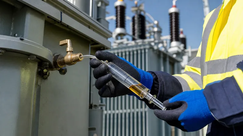
Field personnel must execute liquid extraction strictly adhering to IEC 60475 and ASTM D923 protocols. The objective is obtaining a laminar, bubble-free oil stream from the lower tank sampling valve without exposing the fluid to ambient air, moisture, or direct ultraviolet radiation.
- Clean the drain valve: Remove the protective brass plug, mechanically scrape foreign particulate matter, and thoroughly flush the sampling port with at least 2 to 4 litres of waste oil into a dedicated disposal container.
- Attach sampling apparatus: Connect a flexible, oil-resistant fluoropolymer (PTFE) or Tygon tube to the valve nipple, securing it with an airtight threaded fitting.
- Purge the collection line: Allow oil to run continuously through the tubing until all trapped air bubbles are purged completely from the transfer line.
- Fill the gas-tight glass syringe: Fit a 50 ml ground-glass syringe equipped with a matched three-way stopcock to the tubing. Allow internal tank static pressure to gently push the syringe plunger outward without pulling manually, which induces cavitation.
- De-gas the syringe: Invert the syringe vertically, tap the glass barrel to release microscopic bubbles toward the nozzle, and expel 5 ml of fluid through the waste port of the three-way stopcock.
- Seal and label: Close the stopcock valve securely, slip a mechanical plunger stop over the shaft to prevent plunger movement during shipment, and record top-oil temperature, ambient temperature, sampling date, and transformer serial data.
Samples must be protected inside opaque, padded transit containers and dispatched to an accredited testing laboratory within 48 hours to prevent gas absorption or photo-oxidation.
Online DGA Monitoring System vs Laboratory DGA Oil Test
Modern substation asset maintenance combines manual laboratory testing with an automated dga monitoring system to capture transient gas generation spikes.
Periodic laboratory testing per ASTM D3612 provides high analytical precision across all hydrocarbon species but suffers from latency; slow-developing or sudden faults occurring between annual inspection cycles remain unnoticed. Conversely, an online dga transformer monitoring installation tracks gas evolution continuously at intervals as short as one hour, alerting remote operations teams to sudden gas rate-of-change spikes.
| Operational Parameter | Laboratory Gas Chromatography | Multi-Gas Online DGA Monitor | Single-Gas / Early Warning Monitor |
|---|---|---|---|
| Measurement Principle | Vacuum extraction with gas chromatography (GC) | Photoacoustic spectroscopy (PAS) or micro-GC | Solid-state semiconductor or catalytic fuel cell |
| Monitored Gases | All 7 key fault gases + atmospheric a standard unit | 5 to 9 gases (H2, CH4, C2H6, C2H4, C2H2, CO, CO2) | Primarily Hydrogen (H2) or Total Combustibles |
| Measurement Frequency | Annual or bi-annual discrete sampling | Configurable: 1 to 4 readings per day | Continuous, real-time analog/digital loop |
| Accuracy & Limits | High precision (± 1 ppm detection limit) | High (± 5% to 10% depending on species) | Moderate (± 15% to 20%, cross-sensitive) |
| Capital Cost | Negligible upfront cost; recurring lab fees | High capital investment per transformer | Low to moderate capital investment |
| Asset Application | All distribution and power transformers | Critical transmission transformers (> 50 MVA) | Standard power transformers (10 - 40 MVA) |
Engineers integrating intelligent assets into modern SCADA architectures can consult our comprehensive transformer monitoring engineering guide for integration details concerning Modbus, DNP3, and IEC 61850 protocol mapping.
Gas Generation Rates and Transformer Action Thresholds
Determining whether a transformer requires immediate de-energisation depends more on the gas generation rate than on absolute dissolved gas concentrations alone.
IEEE C57.104-2019 Table 1 defines 95th percentile cumulative gas limits, categorising assets into Status 1 (Normal), Status 2 (Elevated), and Status 3 (Severe). However, a historical transformer operating stably for decades may exhibit elevated baseline methane or ethane levels without an active internal fault. A sudden increase in the rate of gas generation—expressed in cubic centimetres per day or ppm per month—signals active energy dissipation inside the tank.
When an active fault develops, maintenance engineers execute the following action sequence per standard operating procedures:
- Rate calculation: Compute the daily generation rate using formula ΔG = (G2 - G1) / (T2 - T1), where G represents concentration in ppm and T represents elapsed days.
- Status 1 (Normal baseline): Gas generation rates remain below 0.5 ppm/day for total hydrocarbon gases. Continue regular annual sampling per the structured transformer maintenance guide.
- Status 2 (Moderate escalation): Rate exceeds 1.5 ppm/day of combustible gases. Increase manual sampling frequency to monthly or commission a portable multi-gas analyzer to verify trajectory.
- Status 3 (Active emergency): Generation rate exceeds 5 ppm/day of ethylene (C2H4) or any detectable increase in acetylene (C2H2). Immediately reduce electrical loading, isolate tap changer operations, perform acoustic partial discharge location, and schedule de-energisation for visual core inspection.
Next steps: specifying and sourcing
When specifying new substation equipment or factory acceptance testing routines, incorporating rigorous dissolved gas thresholds guarantees long-term operational integrity. Ensure your technical procurement schedules explicitly require pre-shipment DGA oil testing under IEC 60076-1 factory acceptance regimes to establish baseline fingerprint gas levels. For critical high-voltage substations, specify multi-gas online diagnostic monitors compatible with plant SCADA systems. Our engineering team designs and manufactures high-efficiency power transformers and robust oil-immersed transformers fully configured with high-integrity sampling ports and digital diagnostic provisions. Submit your detailed single-line diagrams, kVA/MVA ratings, and monitoring requirements via our transformer quote page to obtain technical specifications and project pricing.
Frequently asked questions
What is DGA in transformer testing?
DGA stands for dissolved gas analysis, a diagnostic laboratory and online testing procedure that measures concentrations of gases dissolved in transformer oil. It detects internal electrical and thermal faults—such as arcing, partial discharges, and hot spots—before major asset failure occurs.
What are the key gases measured in transformer DGA?
The seven primary fault gases measured are hydrogen (H2), methane (CH4), ethane (C2H6), ethylene (C2H4), acetylene (C2H2), carbon monoxide (CO), and carbon dioxide (CO2). Non-fault atmospheric gases such as oxygen (O2) and nitrogen (N2) are also tracked.
Why is acetylene critical in a DGA oil test?
Acetylene forms almost exclusively at temperatures above 700°C, which are typical of high-energy electrical arcing and severe dielectric breakdown. Even trace levels exceeding 1 to 2 ppm indicate high-voltage flashovers or turn-to-turn shorts requiring immediate operational investigation.
How does the Duval Triangle work in transformer DGA analysis?
The Duval Triangle 1 method plots the relative percentage concentrations of methane, ethylene, and acetylene on a triangular graphic grid. The resulting coordinate pinpoints specific internal defect zones, differentiating between low- and high-energy arcing, partial discharge, and varied thermal overheating tiers.
How often should transformer oil undergo DGA testing?
Standard operational transformers undergo laboratory DGA testing annually or semi-annually per IEEE C57.104 recommendations. Highly critical transmission units or units showing rising gas trends are monitored continuously via online multi-gas extraction systems or sampled on monthly cycles.
Tags: dga transformer dissolved gas analysis transformer dissolved gas analysis dga oil test dga monitoring system


