Key takeaways
- DC arcs have no natural current zero, so DC breakers need DC voltage and breaking ratings under IEC 60947-2, IEC 60898-2 or UL 489 with DC marking.
- Voltage drop dominates 12 V design: a 20 A load 6 m from the battery needs about 16 mm² copper to stay near 2 percent drop.
- Raising system voltage from 12 V to 48 V cuts current by a factor of four for the same power and reduces conductor losses by a factor of sixteen.
- Lithium batteries can deliver several kiloamperes into a short circuit, so the main fuse at the battery must have an adequate DC interrupting rating.
- Substations rely on 110 V or 220 V DC panels fed by a battery and charger to trip breakers and power relays when AC auxiliary supply is lost.
Quick answer: A DC distribution panel takes power from a battery, rectifier or DC bus and divides it into fused or breaker-protected circuits for DC loads. Panels range from 12 V and 24 V boards in vehicles and boats, through 48 V telecom and battery systems, to 110 V and 220 V DC panels feeding substation protection. Every device must carry a DC voltage rating.
DC distribution looks simpler than AC: two conductors, no phases, no power factor. In practice it is less forgiving. Low voltages mean high currents and painful voltage drop, batteries supply enormous fault currents with no utility impedance to limit them, and breakers that interrupt AC easily can fail to clear a DC arc.
This guide is for engineers and technicians specifying a DC breaker panel for vehicles, vessels, telecom shelters, battery systems or substation auxiliary supplies. It compares voltage classes, explains what makes DC protection different, works through voltage drop and fault current examples, and lists what to include in a specification.
What Is a DC Distribution Panel?
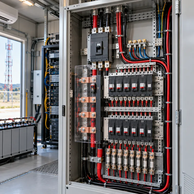
A DC distribution panel is an enclosure containing a positive and negative (or grounded) bus, a main disconnect or fuse, and individual DC-rated breakers or fuses that feed separate DC circuits. A dc panel, dc breaker box or dc circuit breaker box all describe the same function.
Typical components:
- Main overcurrent device close to the battery, often a high-interrupting-capacity fuse.
- Positive bus feeding branch breakers or fuses.
- Negative bus, which may be bonded to ground or chassis, or kept isolated in floating systems.
- Branch devices: thermal-magnetic DC breakers, hydraulic-magnetic breakers or blade fuses.
- Metering: voltmeter, ammeter via a shunt, and often battery state-of-charge monitoring; see our battery shunt monitor guide.
- Insulation monitoring in unearthed systems, to detect the first ground fault before a second one causes a short.
The panel may be fed by a battery, a rectifier or charger, a DC-DC converter, or a solar charge controller. In larger systems the source is a battery bank with its own disconnect, as described in our lithium battery bank guide. The design approach is the same as for an AC power distribution board: size for continuous current, fault current and selectivity, but with DC-specific device ratings.
DC Voltage Classes and Where Each Is Used
The application sets the voltage. Each class has typical sources, standards and protection practice.
| Nominal voltage | Typical applications | Source | Protection practice |
|---|---|---|---|
| 12 V | RVs, boats, vehicles, small off-grid | Lead-acid or LFP battery | Blade fuses, thermal breakers, main fuse at battery |
| 24 V | Trucks, larger vessels, control circuits | Battery, 24 V power supplies | DIN-rail DC MCBs, electronic circuit protection |
| 48 V (often −48 V) | Telecom, data, battery inverters, light EVs | Rectifier plus battery string | DC MCBs, telecom fuses, low-voltage disconnect |
| 110 / 125 V | Substation and switchgear control, tripping | Station battery and charger | 2-pole DC MCBs, insulation monitoring |
| 220 / 250 V | Power plants, large substations | Station battery and charger | 2-pole DC MCCBs, fuses |
| 600–1,500 V | PV arrays, battery energy storage, traction | PV strings, battery racks | DC switch-disconnectors, gPV fuses, DC MCCBs |
Telecom systems traditionally use −48 V: the positive bus is grounded and the negative bus is live, which reduces electrolytic corrosion of buried cable sheaths. A 48v dc distribution panel for telecom therefore switches and fuses the negative conductor, the opposite of most vehicle and marine systems. Check grounding polarity before ordering any panel. For battery-side design at 48 V, our 48 V battery engineering guide covers string sizing.
Why DC Circuit Breaker Panels Need DC-Rated Devices
An AC breaker interrupts current at a natural zero crossing 100 or 120 times per second. DC has no zero crossing, so the breaker must stretch and cool the arc until its voltage exceeds the system voltage. That is why a dc circuit breaker panel uses devices designed and tested for DC.
What to check on every device:
- Rated DC voltage per pole. Many AC miniature breakers carry a DC rating only at reduced voltage, for example 48 V or 60 V per pole; higher voltages require poles in series.
- DC breaking capacity at the circuit's time constant. IEC 60898-2 and IEC 60947-2 test DC breaking at defined L/R values; inductive loads such as solenoids and motors are harder to interrupt.
- Polarity. Some DC breakers use permanent magnets to blow the arc into the chute and only work in one direction. Reverse them and they may fail to interrupt; never use them where current can flow both ways, such as battery charge and discharge circuits, unless marked non-polarized.
- Listing: UL 489 breakers with a DC marking, UL 489B for PV circuits, UL 248 fuses with DC ratings, or ABYC E-11 compliance for marine panels.
Using an AC-only breaker on DC is a common and dangerous mistake in DIY battery systems. The breaker may weld or sustain an arc inside the case. For a broader comparison of breaker technologies, see our circuit breaker types guide.
Sizing a 12 Volt DC Circuit Breaker Panel: Voltage Drop Example
In a 12 volt dc distribution panel, conductor size is almost always set by voltage drop rather than ampacity. Use the round-trip length, because current flows out on the positive and back on the negative:
Vd = I × ρ × (2 × L) / A, with copper resistivity ρ ≈ 0.0175 Ω·mm²/m at operating temperature, L the one-way length in meters and A the cross-section in mm².
Given: a 20 A refrigerator compressor and pump circuit, 6 m one-way from a 12.8 V LFP battery bank.
- Try 4 mm²:
Vd = 20 × 0.0175 × 12 / 4 = 1.05 V, which is 8.2 percent. Too high for a compressor. - Try 10 mm²:
Vd = 20 × 0.0175 × 12 / 10 = 0.42 V, 3.3 percent. - Try 16 mm²:
Vd = 20 × 0.0175 × 12 / 16 = 0.26 V, 2.1 percent. Select this for a sensitive motor load. - Breaker: protect the conductor, not the load. A 25 A or 30 A DC breaker suits 16 mm² cable and the 20 A load with start-up margin.
Marine practice under ABYC E-11 targets 3 percent drop for critical circuits such as navigation lights and bilge pumps, and up to 10 percent for non-critical loads. The same 20 A load on a 48 V system draws only 5 A for equal power, so 2.5 mm² gives 0.42 V, under 1 percent. That is the main reason larger systems move up to 24 V or 48 V.
| Copper size | Drop at 12 V, 20 A | Drop at 48 V, 5 A |
|---|---|---|
| 2.5 mm² | 1.68 V (13.1%) | 0.42 V (0.9%) |
| 4 mm² | 1.05 V (8.2%) | 0.26 V (0.5%) |
| 10 mm² | 0.42 V (3.3%) | 0.11 V (0.2%) |
| 16 mm² | 0.26 V (2.1%) | 0.07 V (0.1%) |
Battery Fault Current and Main Fuse Selection
A battery is a near-ideal voltage source with very low internal resistance, and nothing upstream limits fault current. The prospective short-circuit current is approximately:
Isc = V / (Rbattery + Rcable)
Example: a 12.8 V LFP bank with an internal resistance of 2 mΩ and 1 mΩ of cable to the panel: Isc = 12.8 / 0.003 ≈ 4,270 A. A 48 V bank built from the same cells in series has four times the voltage and four times the resistance, so the fault current is similar, but the arc energy and voltage across the opening device are four times higher.
Consequences for the dc power distribution panel:
- Install the main fuse as close to the battery positive terminal as practical; marine and vehicle standards set maximum distances.
- Choose a fuse whose DC interrupting rating exceeds the calculated Isc with margin; high-interrupting-capacity fuse classes rated in the tens of kiloamperes are used on lithium banks.
- Verify that branch breakers are either rated for the full fault current or protected by the upstream fuse in a tested series combination.
- Obtain the battery manufacturer's declared short-circuit current rather than estimating from cell data.
Battery management systems add electronic protection, but a BMS contactor is not a substitute for a fuse rated to interrupt the full fault. Our stationary battery systems guide covers protection layering in larger installations.
Substation DC Panels: 110 V and 220 V Auxiliary Systems
Every substation depends on a DC system. When a fault collapses AC voltage, protection relays still need power to detect it and breaker trip coils still need energy to open. A substation DC system is a battery, a charger and a DC distribution board that supply protection, control, communications and emergency lighting independently of the AC auxiliary supply.
Design features that differ from mobile DC panels:
- Nominal voltage of 110 V or 125 V DC for most distribution substations, 220 V or 250 V for large stations.
- Unearthed (floating) bus with an insulation monitoring device, so a single ground fault raises an alarm without tripping.
- Two-pole breakers on every circuit, with selectivity between incomer and branch devices.
- Battery sizing to a duty cycle per IEEE 485 for lead-acid or IEEE 1115 for nickel-cadmium, covering continuous load, momentary trip loads and an autonomy period, often 2 to 8 hours.
- Redundancy on critical stations: two batteries, two chargers and duplicate trip circuits.
Medium-voltage switchgear and ring main units specify their control voltage, typically 110 V or 220 V DC, for motor operators, trip coils and relays. The DC auxiliary system must be designed together with the switchgear, as covered in our substation auxiliary power guide and the substation protection guide.
Next Steps: Specifying and Sourcing DC Distribution
A DC distribution specification should state:
- Nominal voltage, range and grounding: positive grounded, negative grounded or floating.
- Source: battery chemistry and capacity, charger rating, declared battery short-circuit current.
- Circuit schedule: each load, current, cable length and whether it is critical.
- Device ratings: DC voltage per pole, DC breaking capacity, polarity and listing.
- Monitoring: shunt metering, insulation monitoring, alarms and communication.
- Enclosure: ingress rating, mounting and cable entry.
MARS does not sell stand-alone 12 V or RV breaker panels. We supply the equipment where large DC systems sit: medium-voltage switchgear designed for 110 V or 220 V DC control supplies, substations whose auxiliary systems are engineered with the switchgear, and LFP battery energy storage with integrated DC protection, BMS and PCS from 93 kWh cabinets to 10 MWh containers. Lead times are typically 25 to 45 days for switchgear and 60 to 90 days for BESS. See our HV and LV switchgear and energy storage systems, then send project details through the quote form.
Frequently asked questions
Can I use an AC breaker in a DC breaker panel?
Only if the breaker carries a DC rating for your voltage and current. Many AC breakers are not tested for DC, and without a current zero they may fail to extinguish the arc. Use breakers marked for DC per IEC 60947-2, IEC 60898-2 or UL 489 with DC rating, and check polarity requirements.
What size wire do I need for a 12 volt DC distribution panel?
Size by voltage drop using Vd = I × 0.0175 × 2L / A in mm². For example, a 20 A load 6 m away needs 16 mm² copper for about 2 percent drop. Then pick a breaker that protects that conductor. Feeders from battery to panel usually need 25 to 50 mm².
Why do telecom systems use negative 48 volts?
Telecom DC plants ground the positive bus and make the negative bus live at −48 V. This polarity reduces electrolytic corrosion of buried cables and metal parts. Panels for −48 V systems therefore fuse and switch the negative conductor, unlike most vehicle and marine systems that switch the positive.
Where should the main fuse go in a DC system?
As close to the battery positive terminal as practical, within the distance allowed by the governing standard for vehicles, vessels or stationary systems. The fuse protects the cable between battery and panel, so any unprotected length is exposed to the full battery fault current, which can exceed several thousand amperes.
What is a DC panel in a substation?
A substation DC panel distributes 110 V or 220 V DC from a station battery and charger to protection relays, breaker trip and close coils, control circuits, communication equipment and emergency lighting. It keeps protection working when AC auxiliary supply is lost during a fault.
Is 48V better than 12V for DC distribution?
For loads above roughly 1 kW, yes. At 48 V the current is one quarter of that at 12 V for the same power, so conductor losses fall by a factor of sixteen and smaller cables can be used. 12 V remains common where vehicle or appliance compatibility matters.
Written and reviewed by the MARS application engineering team in Shanghai, who specify and test transformers, switchgear, substations and battery storage for projects in 40+ countries. Last updated .
Tags: dc distribution panel dc breaker panel 12 volt dc distribution panel 48v dc distribution panel dc circuit breaker panel