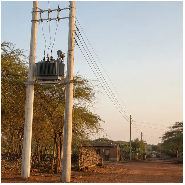
At a glance
| Country | Tanzania |
|---|---|
| Application | Rural distribution network extension |
| System | 11 kV/0.4 kV pole-mounted distribution transformer |
| Voltage | 11 kV incoming / 0.4 kV outgoing |
| Frequency | 50 Hz |
| Standards basis | IEC 60076 series (transformer), IEC 60099-4 (surge arresters), IEC 60282-1 (HV fuses), IEC 60383 (insulators), IEC 61936-1 (AC installations above 1 kV), IEC 60364 practice for the LV network |
| Visual status | Representative project visualization |
The engineering problem
Rural electrification is a voltage-drop and loss problem before it is an equipment problem. Loads are small, scattered and separated by kilometres, so the network’s job is to carry 11 kV as far as possible and convert to 0.4 kV as close to the consumers as it can. Extending LV instead is what causes the classic rural failure mode: acceptable voltage at the transformer and unusable voltage at the last house, with motors that will not start and lamps that dim on every load step.
A pole-mounted transformer answers this because it is a transformation point that needs no land, no fence and no foundation. It can be placed where the load is, and moved or extended as the network grows.
The duty is unusual in one respect. Rural load factor is low — significant demand for a few hours, very little for the rest of the day — so no-load loss, which runs continuously, dominates lifetime energy loss far more than it would on an industrial feeder. Core material and no-load loss figures deserve as much attention as impedance.
The environment then sets the reliability limit. East African feeders see high lightning activity, and a pole-mounted unit sits directly on an exposed overhead line. Surge arresters, their earthing and their lead length are what decide whether the transformer survives the wet season. Dust, humidity, thermal cycling and the practical reality of remote maintenance all argue for a simple, robust arrangement with few failure points.
System configuration
| Item | Description | Specification notes |
|---|---|---|
| Distribution transformer | Pole-mounted 11 kV/0.4 kV oil-immersed unit | Rating, vector group and impedance set by the load study; low no-load loss design is normally worth the premium at rural load factors |
| Pole and mounting structure | Single pole or H-pole platform with mounting brackets | Structure sized for transformer mass, wind loading and conductor tension; ground clearance and public access set by the utility standard |
| Crossarm and insulators | HV crossarm with pin or post insulators, LV rack | Creepage class selected for the pollution level; insulator strength checked against conductor tension and span |
| HV protection | Drop-out expulsion fuses or fuse cut-outs on the 11 kV side | Fuse rating coordinated to pass inrush and permit downstream LV clearance without operating |
| Surge protection | Lightning arresters on the HV side, and on the LV side where the utility standard requires | Arrester earth lead kept as short and straight as possible; rated voltage matched to the system earthing arrangement |
| LV distribution | LV fuse or circuit-breaker board, outgoing feeder connections | Outgoing ways and ratings matched to the LV network layout and expected diversity |
| Earthing | Transformer tank, arrester and neutral earthing, with earth electrode | Electrode arrangement and conductor size chosen for the measured soil resistivity and the required earth resistance |
| Connections and hardware | Conductor connectors, bimetallic interfaces, bird and vermin protection | Aluminium-to-copper joints require a bimetallic interface; connector type matched to conductor size and material |
| Finish and security | Tank coating, tamper-resistant fixings | Coating class chosen for humidity and UV exposure; anti-climb and tamper measures per the utility standard |
Installation sequence
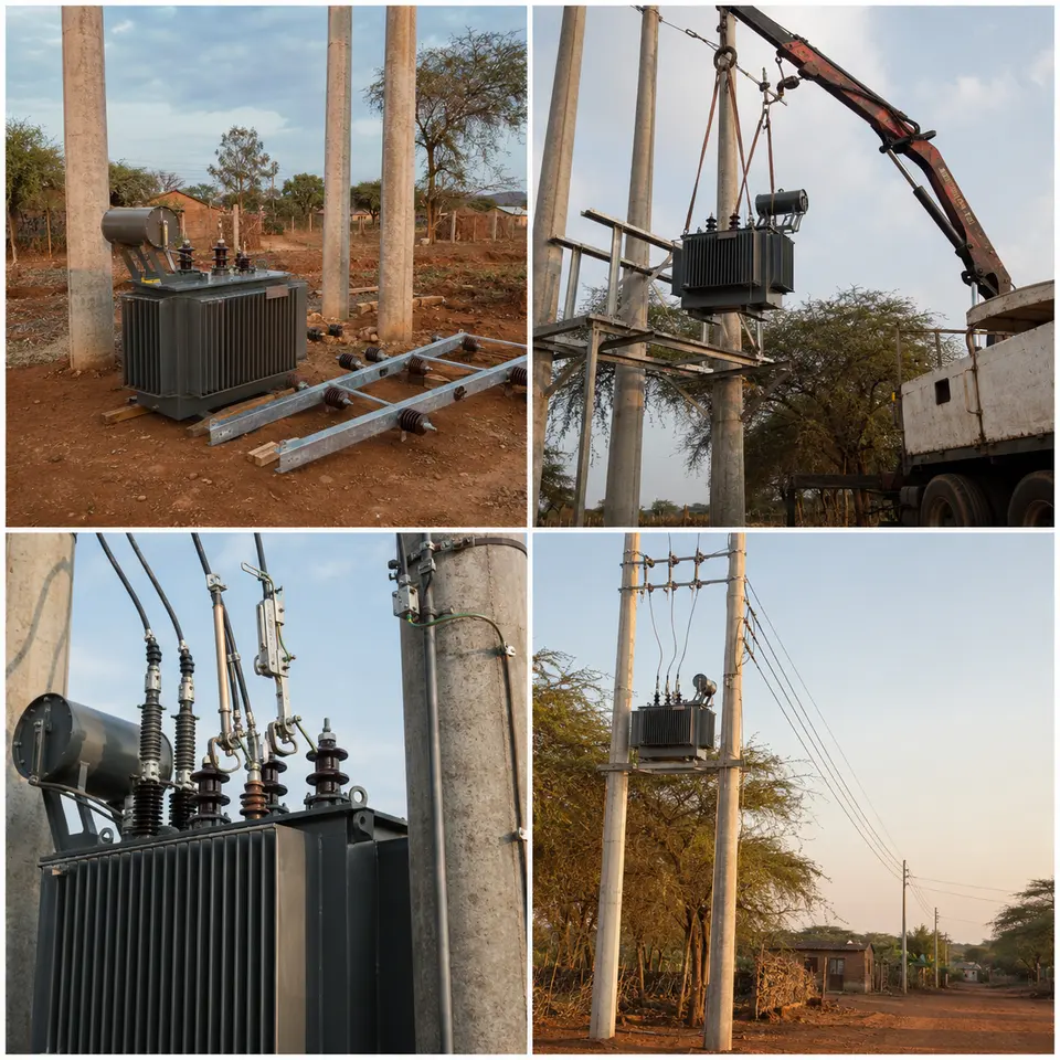
Overview
The contact sheet sets out the four stages of an installation of this type: equipment staging, lifting and mounting on the pole, connection of protection and earthing, and the completed distribution line. The order reflects what can and cannot be reached later. Earth electrode installation and resistance measurement come before the pole structure is fully dressed, because the connection point is awkward to reach afterwards. Mechanical mounting is completed and proved before any conductor is connected, so that no live-side work depends on a bracket that has not been checked. Testing closes the sequence, with the transformer proved before it is connected to the feeder.
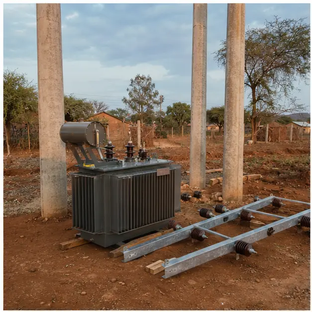
Staging
Staging matters more on rural work than on a compounded site, because a missing bracket or the wrong fuse carrier can cost a day of travel. Equipment is checked against the schedule and inspected for transport damage: tank and radiator surfaces for dents and paint loss, bushings for chips or cracks, oil level and gasketed joints for leakage, and the nameplate against the ordered rating and vector group. Insulation resistance and turns ratio are commonly measured at the staging point rather than at height, where instruments and hands are harder to manage. Poles, crossarms, insulators, fuses, arresters and earthing material are laid out per structure so the installation crew works from a complete set.
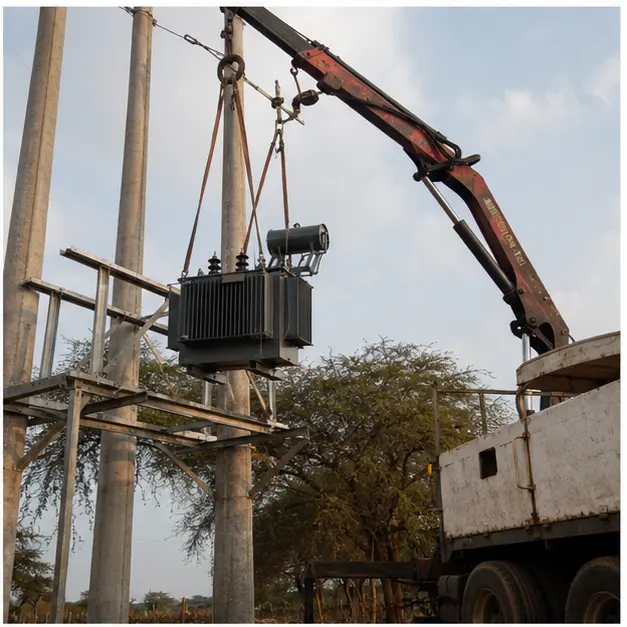
Mounting
Lifting a transformer onto a pole platform is the mechanically critical step. The unit is slung from its designated lifting lugs with the sling angle controlled — a wide angle multiplies the tension in each leg well above the share of the load it appears to carry. The pole and its foundation are confirmed adequate for the added mass and the eccentric moment it creates before the lift, and guying is checked where the structure also carries conductor tension. Mounting brackets are seated flat against the pole and bolted to value, since a bracket that bears on one edge concentrates load and works loose under thermal and wind cycling. Ground clearance is confirmed against the utility standard.
Protection and earthing
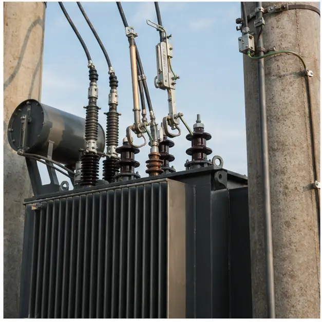
Protection and earthing are where a pole-mounted installation is made or lost. Surge arresters are mounted close to the transformer bushings with the shortest practical earth lead: lead inductance adds a voltage of L·di/dt on top of the arrester’s residual voltage, so a long, looping earth lead can defeat the protection it is supposed to provide. Arrester earth, tank earth and the LV neutral are bonded to the same electrode system to avoid a potential difference appearing across the insulation during a strike. Electrode resistance is measured, not assumed, and additional rods or a counterpoise added where soil resistivity is high. Fuse ratings are checked for coordination, and every connection is made with the correct connector and, where dissimilar metals meet, a bimetallic interface.
Completed configuration
The completed line shows the transformation point in service on the overhead network. Before energisation, turns ratio, vector group and insulation resistance are verified, earth resistance is recorded, and LV phase rotation and voltage are confirmed once the transformer is charged unloaded. Clearances to ground, to structures and to any crossing are checked against the utility standard, and warning signage and identification are fitted. Load is then applied progressively while LV voltage is checked at the far end of the network, because the whole point of the arrangement is voltage at the consumer, not at the transformer. Connector temperatures are worth a thermographic check once load is established.
Specification options
For a comparable rural enquiry, MARS can configure the voltage ratio and tapping range, capacity, vector group and impedance, with copper or aluminium windings and a low no-load loss core where the load factor justifies it. Units can be supplied as conventional pole-mounted transformers or, where the utility standard requires, with integral protection. Bushing creepage can be raised for polluted or coastal conditions, and tank coating specified for humidity, UV and corrosion class. Fuse cut-outs, lightning arresters, crossarms, insulators, LV boards and connection hardware can be supplied as a matched set to the utility’s standard drawing. Temperature-rise limits and overload capability can be set for the site ambient, and monitoring can extend to oil-level and temperature indication where the network operator collects that data.
What we need to quote a comparable system
Send as many of the following as you have. Missing items are not a problem — we will ask.
- The utility or network operator standard drawing and material specification to be followed
- Incoming 11 kV system details, tapping range and required vector group
- Outgoing LV voltage, system earthing arrangement and the LV network layout
- Transformer capacity and the expected load profile, including load factor and growth allowance
- System fault level at the point of connection and the fuse or protection coordination required
- Soil resistivity data or the target earth resistance value
- Lightning activity level and any existing arrester specification
- Site ambient temperature range, altitude, humidity and pollution or salinity level
- Pole type, height and mounting arrangement, or confirmation that MARS should propose one
- Conductor type and size for HV and LV connections, so connectors can be matched
- Quantity per structure and total, with any spares or strategic stock requirement
- Delivery terms, destination port, documentation language and required test certificates