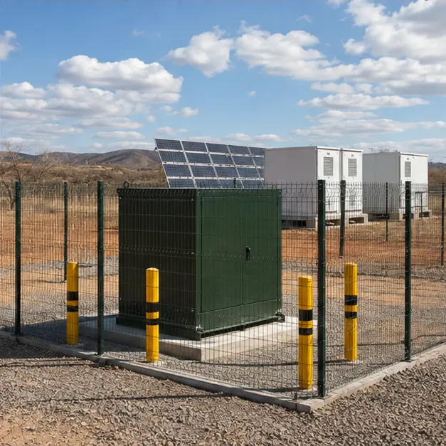
At a glance
| Country | Brazil |
|---|---|
| Location | Bahia (as stated in the source material) |
| Application | Utility photovoltaic power plant |
| System | 34.5 kV/480 V three-phase pad-mounted transformer, dead-front |
| Voltage | 34.5 kV collector / 480 V inverter side |
| Frequency | 60 Hz |
| Standards basis | ABNT NBR 5356 series (power transformers, aligned with IEC 60076), ABNT NBR 5440 and ABNT NBR 14039 for MV installations, IEEE C57.12.34 for three-phase pad-mounted compartmental construction, IEEE 386 for separable insulated connectors, ANEEL PRODIST for distributed connection requirements |
| Visual status | Representative project visualization |
The engineering problem
A Brazilian utility PV plant collects at 34.5 kV. That single number shapes the whole design. It is high enough to move plant-scale power over kilometres of buried collector cable with acceptable loss, and it is the standard Brazilian rural and industrial distribution class, so the equipment, cable, elbows and protection are all available against a mature domestic specification rather than a special.
On the inverter side, 480 V is a working compromise: high enough to keep inverter output current and cable size manageable, low enough to stay within ordinary LV switchgear and cable practice. The transformer that sits between them therefore steps up rather than down, and it spends its life driven by an inverter rather than by a load. That changes the specification. Harmonic current from the inverter adds eddy and stray loss, so a K-factor or harmonic loading assessment belongs in the sizing. The duty cycle is strongly cyclic — full load in the middle of the day, no load at night — which makes no-load loss economically significant across the plant’s whole fleet of transformers and makes thermal cycling, not steady heating, the ageing mechanism. Ratio and vector group must match the inverter manufacturer’s earthing and grounding-transformer requirements, since a PV block is normally earthed on the MV side by the step-up transformer itself.
The dead-front pad-mounted format answers the physical problem. A PV site is a large, publicly bordered, unattended area. A tamper-resistant, sealed, ground-level enclosure with all live parts behind an insulated interface removes exposed terminals from the site entirely, needs no elevated structure, and can be delivered and set with a single lift. It also suits the loop-feed collector topology used to string blocks together.
System configuration
| Item | Description | Specification notes |
|---|---|---|
| Transformer | 34.5 kV/480 V three-phase pad-mounted step-up unit, oil-immersed, hermetically sealed | ABNT NBR 5356 basis; vector group and MV earthing arrangement matched to the inverter's requirement; impedance selected against inverter fault contribution and collector voltage regulation |
| Enclosure | Dead-front compartmental pad-mounted cabinet, tamper-resistant | Separate HV and LV compartments with a defined opening sequence; ISO 12944 coating category and paint system chosen for solar radiation and site exposure |
| HV interface | Loadbreak or deadbreak separable connectors on bushing wells, loop-feed or radial | IEEE 386 elbows with capacitive test points and parking stands; loop-feed arrangement lets a block be isolated without dropping the collector run |
| HV protection | Bayonet and backup current-limiting fuses, or an internal switch with fusing | Fuse coordination set against inverter transformer inrush and the upstream collector protection |
| LV interface | 480 V spade or bar terminals in the LV compartment, multiple inverter cable ways | Terminal count and cable entry sized to the inverter cable arrangement; non-magnetic gland plates where single-core cables are used |
| Surge protection | MV surge arresters, elbow-type or bracket-mounted | Rating and energy class selected against the collector system earthing and the local lightning density, which is high across much of Brazil |
| Thermal design | Radiators or corrugated tank walls, sealed oil system with no conservator | Temperature rise limits set for the design ambient and the cyclic PV duty; harmonic loading from inverters accounted for in loss calculation |
| Earthing | Tank, enclosure, arrester and cable screen bonding to the site earth grid | Conductor sized for prospective earth-fault current and clearing time; step and touch potential assessed for a publicly accessible pad |
| Monitoring | Oil temperature, level and pressure indication, optional contacts to the plant SCADA | Alarm and trip contacts wired to the plant control system where an arrangement of this type is remotely supervised |
Installation sequence
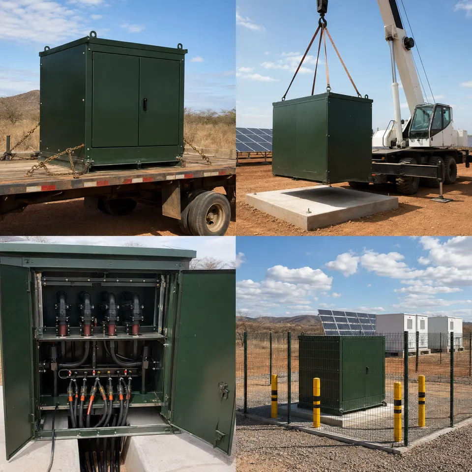
Overview
The contact sheet sets out the four stages of an installation of this type: delivery to the block position, crane placement onto the pad, dead-front cable connection, and the completed fenced installation. The sequence is governed by the concrete. The pad, its cable stub-ups, the conduit entries and the earth grid connections all have to be complete, cured and surveyed before the transformer lands, because the underside of a pad-mounted unit is unreachable afterwards. Cable is pulled and left long, terminated only once the transformer is set and its bushing positions are known. Testing that requires the compartments open is finished before the enclosure is closed, locked and the block handed to the commissioning team.
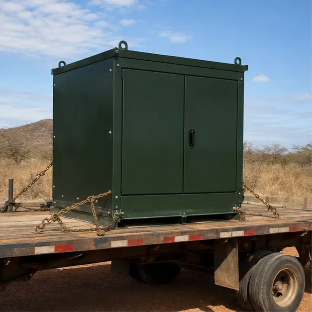
Delivery
Delivery to a PV block is a low-speed, off-road transport problem. Internal plant roads are usually unsealed, and a pad-mounted transformer carries its mass low but concentrated, so lashing must restrain lateral movement rather than merely hold the unit down against its own weight. Where a unit has been transported over long distances, an impact recorder is worth reading on arrival. Receiving inspection covers transport damage, paint integrity — a coating scratch on a Bahia site becomes a corrosion site quickly — oil level in the sight glass, pressure-vacuum gauge reading, bushing and bushing-well condition, and the presence of the elbows, parking stands and arresters listed on the packing note. Any positive or negative internal pressure is recorded before the tank is opened.
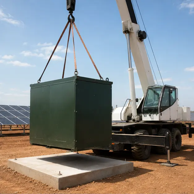
Placement
Placement is a single, short lift, but it is unforgiving. The pad is confirmed level and its cable window checked against the transformer footprint before the lift, since a pad-mounted unit set out of level will not drain water from its roof and will load its gasketed joints unevenly. Lifting uses the four designated lugs with a spreader so slings do not bear on radiators, bushings or the cabinet. Crane capacity is assessed at working radius with outrigger bearing pressure checked on the ground actually available — soft ground beside a new pad is a common cause of an aborted lift. The unit is landed clear of the stub-up cables, aligned so the HV and LV compartments face the intended access side, and anchored to the pad.
Cable work
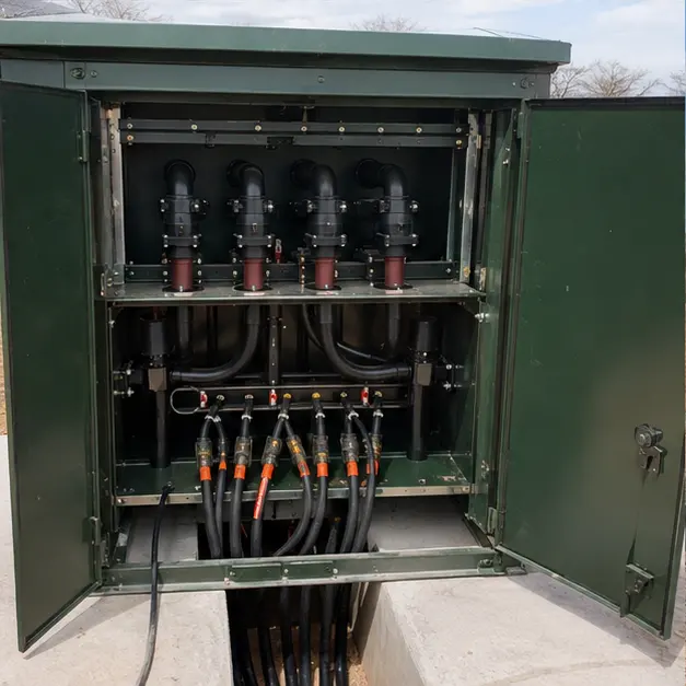
The dead-front interface is the reason this format is used, and it is also where the workmanship risk sits. Cable is cut to length with the bending radius into the compartment respected — a 34.5 kV cable forced round a tight radius damages its insulation shield and fails later, not immediately. Elbow preparation follows the same discipline as any MV termination: correct cut-back, semiconducting layer removal, cleanliness, and the specified lubricant, with the connector fully seated so the capacitive test point reads correctly. Elbows are only operated with a hotstick against the loadbreak rating; deadbreak connectors are not switched at all. Cable screens and the arrester earths are bonded to the site grid with a conductor rated for the earth-fault duty. LV terminals are torqued to value and marked.
Completed configuration
Before energisation the block is proved as a chain. Turns ratio is measured on every tap and the vector group verified, since a wrong group on one block of a multi-block PV plant will not show until the inverters attempt to synchronise. Winding and insulation resistance are recorded, oil condition and dielectric strength are confirmed, and earth continuity is proved from the tank, cabinet, arrester bases and cable screens back to the site grid, with the grid resistance recorded. Fuses are checked for correct rating, protection grading against the collector feeder is confirmed, and the enclosure is closed and locked. Energisation is staged — collector feeder first, transformer charged from the MV side unloaded, then inverters brought on progressively as irradiance allows.
Specification options
For a comparable PV enquiry, MARS can configure capacity, primary and secondary voltage, tapping range, vector group and impedance against the inverter manufacturer’s requirement and the collector system study, with copper or aluminium windings. Transformers can be supplied hermetically sealed or with a conservator, with mineral oil or a less flammable ester fluid where fire separation distances are tight, and with temperature rise and insulation class set for the design ambient and the cyclic PV duty. Dual-secondary and split-winding arrangements can be provided where two inverters share one unit. Enclosures can be specified for coating system and corrosion category, tamper-resistant hardware, loop-feed or radial HV interface, loadbreak or deadbreak elbows, bayonet plus backup fusing or an internal switch, and integrated surge arresters. Monitoring can extend to oil temperature, level and pressure contacts, winding temperature indication, and reporting over Modbus, IEC 61850 or DNP3.
What we need to quote a comparable system
Send as many of the following as you have. Missing items are not a problem — we will ask.
- Single-line diagram of the collector system showing the block arrangement and loop-feed topology
- Transformer capacity per block and the number of units required
- Primary and secondary voltage, tapping range, required vector group and MV earthing arrangement
- Inverter make, model, output arrangement and its transformer requirements, including harmonic content
- Collector system fault level, protection philosophy and the upstream feeder relay settings
- Site ambient temperature range, solar radiation exposure, altitude, dust and lightning density
- Distribuidora or concessionária connection specification and any ANEEL PRODIST requirements applying
- HV interface type — loadbreak or deadbreak elbows, bushing well arrangement, parking stands
- LV terminal arrangement, cable size and number of cable ways per phase
- Enclosure coating and corrosion class, tamper-resistant hardware requirement, and pad detail
- Monitoring contacts, communication protocol and the plant SCADA points list
- Site access route, permissible axle loading, available crane capacity and delivery terms