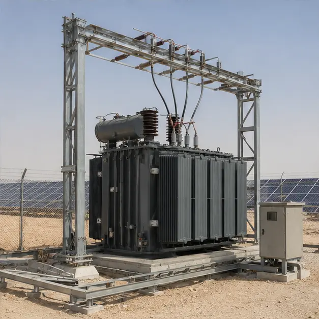
At a glance
| Country | Saudi Arabia |
|---|---|
| Application | Utility-scale photovoltaic power station |
| System | 33 kV/13.8 kV oil-immersed power transformer bay |
| Voltage | 33 kV / 13.8 kV |
| Frequency | 60 Hz |
| Standards basis | IEC 60076-1/-2/-3/-5/-7 (transformer, temperature rise, insulation, short circuit, loading), IEC 60137 (bushings), IEC 60099-4 (surge arresters), IEC 61936-1 (AC installations above 1 kV), IEC 60815 (creepage for polluted conditions) |
| Visual status | Representative project visualization |
The engineering problem
A transformer bay at a Saudi photovoltaic plant works in three conditions that a general-purpose distribution unit is not designed around.
The first is ambient temperature. Temperature rise under IEC 60076-2 is defined above ambient, so a site with sustained high daytime air temperature consumes the hot-spot margin before any load is applied. The rating, the oil and winding rise limits, and the radiator surface all have to be set against the site’s design ambient rather than the standard reference values.
The second is the load shape. A PV plant produces nothing overnight, ramps up through the morning and can sit near full output for hours. That is a cyclic duty, and it should be assessed with the IEC 60076-7 loading guide, using the thermal time constants of the actual design, rather than treated as continuous rated load. Inverter output also carries harmonic content, which raises eddy and stray losses above the sinusoidal case and lifts the hot-spot temperature for the same rms current.
The third is the environment. Airborne dust and sand contaminate insulator and bushing surfaces, so creepage distance is chosen for a heavy pollution class, and radiator fins and cooler intakes need to stay cleanable. UV and thermal cycling attack gaskets and paint, so coating class and gasket material are part of the electrical specification, not an afterthought.
Operating at 60 Hz is straightforward but not neutral: core flux density falls for the same applied voltage and turns, while eddy-current and stray losses rise with frequency, and reactance scales with it. A design of this type is specified at 60 Hz from the outset rather than adapted from a 50 Hz unit.
System configuration
| Item | Description | Specification notes |
|---|---|---|
| Power transformer | Oil-immersed 33 kV/13.8 kV step-up unit for PV export | Rating, impedance and vector group set by the plant's inverter block layout and the grid connection study |
| Cooling | Radiator bank, ONAN or ONAF with fan control | Radiator surface and fan staging sized on the site design ambient and the daily PV load cycle, not on standard reference ambient |
| Oil preservation | Conservator with air dryer or sealed system | Conservator volume covers the oil expansion range across the full day-to-night temperature swing |
| Bushings and terminations | HV and MV bushings with connection to the station gantry | Creepage class selected for heavy pollution; connectors sized for both current and mechanical load from conductor and wind |
| Surge protection | Arresters on the HV and MV sides | Rated and continuous operating voltage selected against the system earthing arrangement and expected temporary overvoltage |
| Protection and monitoring | Buchholz relay, oil and winding temperature indication, pressure relief, oil level, differential and overcurrent protection | Contacts wired to the plant protection and SCADA; winding temperature used for fan control and alarm |
| Earthing | Station earth grid, tank and neutral earthing, gantry bonding | Conductor sized for prospective fault current and clearing time; step and touch potential verified for the bay layout |
| Foundation and containment | Reinforced plinth, rails or pads, oil containment and drainage | Containment volume matched to the oil quantity and local environmental requirement |
| Enclosure and finish | Outdoor construction, coating and hardware | Coating class and gasket material selected for UV, sand abrasion and wide diurnal temperature swing |
Installation sequence
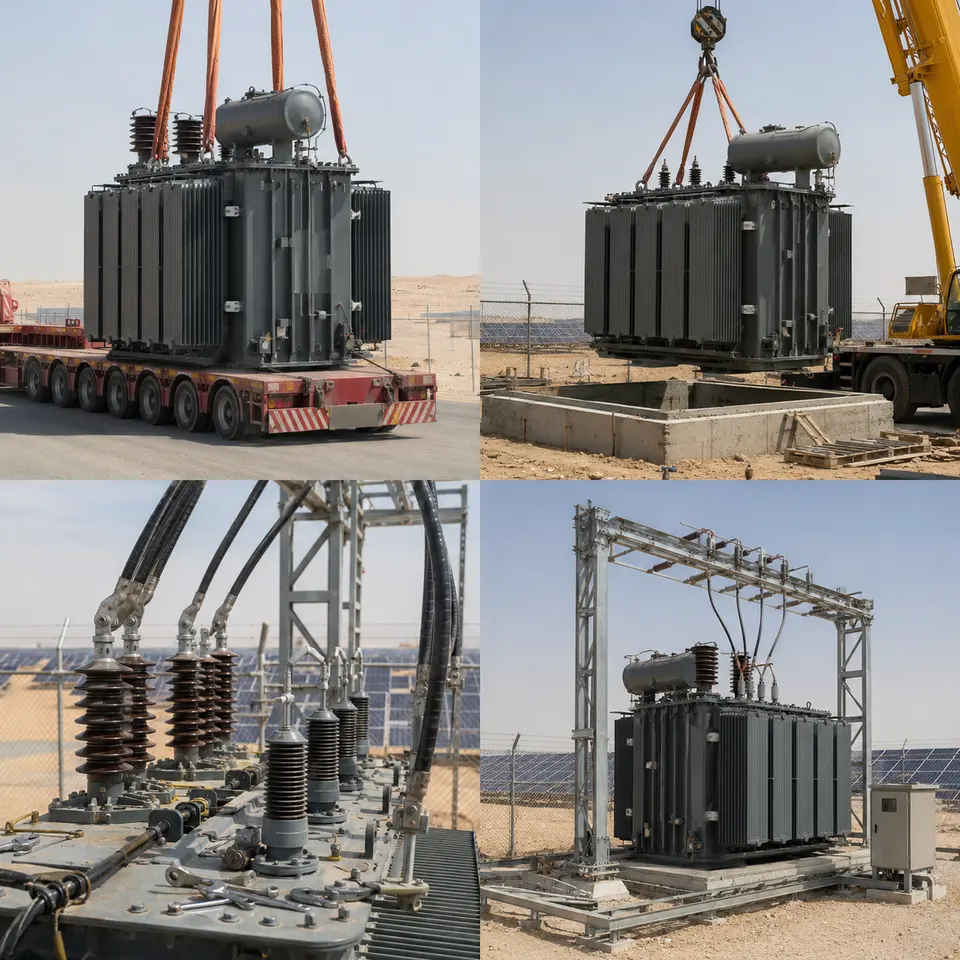
Overview
The contact sheet sets out the four stages of a bay installation of this type: transport and delivery, crane placement, high-voltage termination work, and the completed bay. The sequence is fixed by physical dependency. The foundation, earth grid and oil containment must be complete and proved before the transformer lands, because parts of them become inaccessible under the tank. Radiators, conservator and bushings are fitted after placement so the transport mass and profile stay within road limits. Terminations follow, because their geometry depends on where the unit actually sits. Testing then closes the sequence, before the bay is fenced and released for energisation.
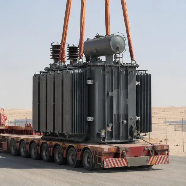
Delivery
A power transformer of this size travels partly dismantled: radiators, conservator and sometimes bushings are shipped separately, and the tank may travel under dry-air or nitrogen pressure rather than filled with oil. Delivery checks are therefore about transport integrity. Impact recorders are read against the agreed shock limits, gas pressure is confirmed to be positive, and gasketed joints and blanking plates are inspected for leakage. The access route matters as much as the load itself: axle loading, bridge capacity, overhead clearance and turning radii on a desert site road are assessed before the vehicle is dispatched, not on arrival.
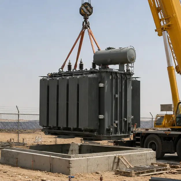
Placement
Placement is the governing lift. Rigging uses the manufacturer’s designated lugs, with the sling geometry arranged so the resultant passes through the centre of gravity — mass in a transformer is concentrated at the core and windings, which are rarely at the tank’s geometric centre. Crane capacity is assessed at the working radius, on ground whose bearing pressure has been checked under the outriggers, and wind speed is monitored because a large tank presents substantial sail area. The plinth is levelled before the unit is set down; out-of-level seating distorts gasket compression at cover and radiator flanges and makes the oil-level gauge read incorrectly.
Terminations
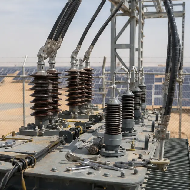
Termination work decides the long-term reliability of the bay. Bushing surfaces are cleaned and their creepage kept clear of conductive dust before connection. Connectors are matched to the conductor material — aluminium to copper needs a bimetallic interface or the joint will corrode and heat — and every bolted connection is torqued to value and recorded. Contact resistance is measured rather than assumed. Connections to the station gantry allow for thermal expansion and for wind and short-circuit forces, so flexible connectors are used where the conductor would otherwise load the bushing stem. Arresters are mounted with the shortest practical earth lead, since lead inductance adds directly to the protective level seen by the transformer.
Completed configuration
The completed bay is proved as a system before energisation. Turns ratio, winding resistance, vector group, insulation resistance and, where specified, oil dielectric strength and moisture content are measured and recorded. Earth grid resistance is measured and continuity from tank, fence and gantry to the grid is confirmed. Protection is tested end-to-end by injection so that relay, CT circuit and trip coil are proved as one chain, and Buchholz, pressure relief and temperature contacts are functionally checked. Fencing, clearances, signage and access control complete the safety case. Energisation is then staged, with the unit charged unloaded first and inverter blocks brought on progressively while temperatures are monitored.
Specification options
For a comparable solar step-up enquiry, MARS can configure the voltage ratio and tapping range, off-circuit or on-load tap changing, capacity, vector group and impedance to suit the grid code and the inverter block arrangement. Windings can be copper or aluminium, with insulation and temperature-rise limits set for a high design ambient and, where required, additional margin for harmonic loading. Cooling can be specified as ONAN, ONAF or a staged combination with automatic fan control. Bushing creepage can be raised for heavy pollution, and coating class, gasket material and hardware finish selected for UV and sand exposure. Accessories can include Buchholz and pressure-relief devices, oil and winding temperature indication, oil-level and dehydrating breather monitoring, online monitoring and IEC 61850, Modbus or DNP3 communication to the plant SCADA.
What we need to quote a comparable system
Send as many of the following as you have. Missing items are not a problem — we will ask.
- Single-line diagram of the plant and the grid connection point
- HV and MV voltages, tapping range, tap changer type and required vector group
- Transformer capacity and the expected daily PV generation profile
- Inverter type and expected harmonic spectrum or K-factor requirement
- Grid fault level, required short-circuit withstand and clearing time
- Neutral earthing arrangement and the protection philosophy, including differential scheme
- Site design ambient temperature range, altitude, wind loading and seismic requirement
- Pollution and dust class, and any salinity exposure, for creepage and coating selection
- Utility or grid operator specification, grid code and approval requirements
- Communication protocol and SCADA points list required
- Foundation, oil containment and gantry interface drawings, plus site access and crane availability
- Delivery terms, destination port, documentation language and required type and routine test certificates