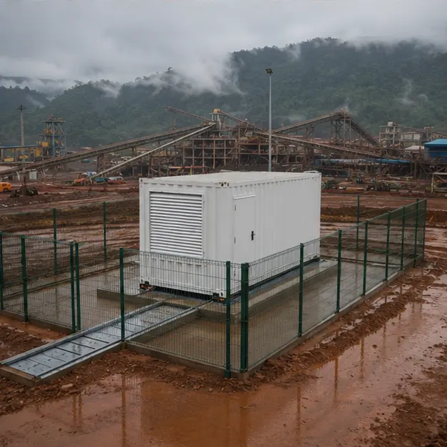
At a glance
| Country | Indonesia |
|---|---|
| Location | Sulawesi (as stated in the source material) |
| Application | Remote mining and mineral-processing facility |
| System | 20 kV/0.4 kV containerized prefabricated substation |
| Voltage | 20 kV incoming / 0.4 kV outgoing |
| Frequency | 50 Hz |
| Standards basis | IEC 62271-202 (prefabricated HV/LV substation), IEC 62271-200 (MV switchgear), IEC 60076 series (transformer), IEC 61439-1/-2 (LV assembly), IEC 60529 (IP), ISO 12944 (corrosion protection of steel structures) |
| Visual status | Representative project visualization |
The engineering problem
Indonesian distribution runs at 20 kV, and a mining or mineral-processing site takes that supply at the edge of a network where support is hours away. Three things follow from that.
First, site labour is the expensive and error-prone part. A containerized substation is integrated and tested in the factory, so what arrives is a proved assembly rather than a kit. On a remote site the value of that is measured in weeks, not in convenience.
Second, the load is motor-dominated. Crushers, mills, conveyors and pumps draw high starting current and, where variable-speed drives are used, inject harmonic current back into the system. Transformer impedance has to be low enough to hold voltage during starting but high enough to keep fault current within the LV switchgear’s withstand rating. That is a genuine trade-off, and it is decided by the plant’s motor schedule, not by a rule of thumb.
Third, the environment is aggressive in several directions at once. Tropical humidity and monsoon rainfall make condensation and water ingress the primary enclosure risks; mineral dust is abrasive and often conductive or hygroscopic; access roads are wet and rutted. A raised foundation, sealed cable entries, controlled ventilation and anti-condensation heating are what keep the equipment inside dry. Sulawesi is also seismically active, so anchoring of the enclosure and of internal equipment is part of the design rather than a site decision.
Relocatability is a fourth, quieter requirement: mine loads move, and a container that can be re-lifted and re-sited has a longer working life than a masonry substation.
System configuration
| Item | Description | Specification notes |
|---|---|---|
| Container enclosure | Factory-integrated outdoor substation container, skid or plinth mounted | IP rating and ISO 12944 corrosion category selected for tropical humidity, rainfall and mineral dust; lifting and re-lifting points designed in |
| MV switchgear | 20 kV incoming and outgoing switching and protection | SF6 or solid-insulated RMU, or air-insulated metal-clad panels where extension and withdrawable breakers are wanted; internal arc classification set for the room layout |
| Transformer | 20 kV/0.4 kV distribution transformer | Cast-resin dry-type where fire load inside the container must be minimised, or oil-immersed with containment; impedance chosen against motor starting and LV fault withstand |
| LV distribution | LV main board and motor or feeder outgoing ways | IEC 61439-1/-2 assembly; form of separation and short-circuit withstand set by the plant fault level and maintenance policy |
| Protection | MV overcurrent and earth-fault relaying, LV main and feeder protection | Grading across MV, transformer and LV stages; earth-fault sensitivity matched to the system earthing arrangement |
| Ventilation and thermal control | Filtered forced ventilation or air conditioning, anti-condensation heating | Sized on total equipment losses at the design ambient; filtration specified against abrasive mineral dust |
| Cable interface | MV entry, LV outgoing entries, gland plates and internal cable routing | Sealed entries maintain the enclosure IP rating; non-magnetic gland plates for single-core LV cables |
| Earthing | Internal earth bar, enclosure and equipment bonding, external electrode connection | Conductor sized for prospective earth-fault current and clearing time; step and touch potential checked for an accessible outdoor location |
| Monitoring and communication | Temperature, door, alarm and status contacts, optional gateway | Modbus RTU/TCP, IEC 61850 or DNP3 where an arrangement of this type reports to a mine-wide control system |
Installation sequence
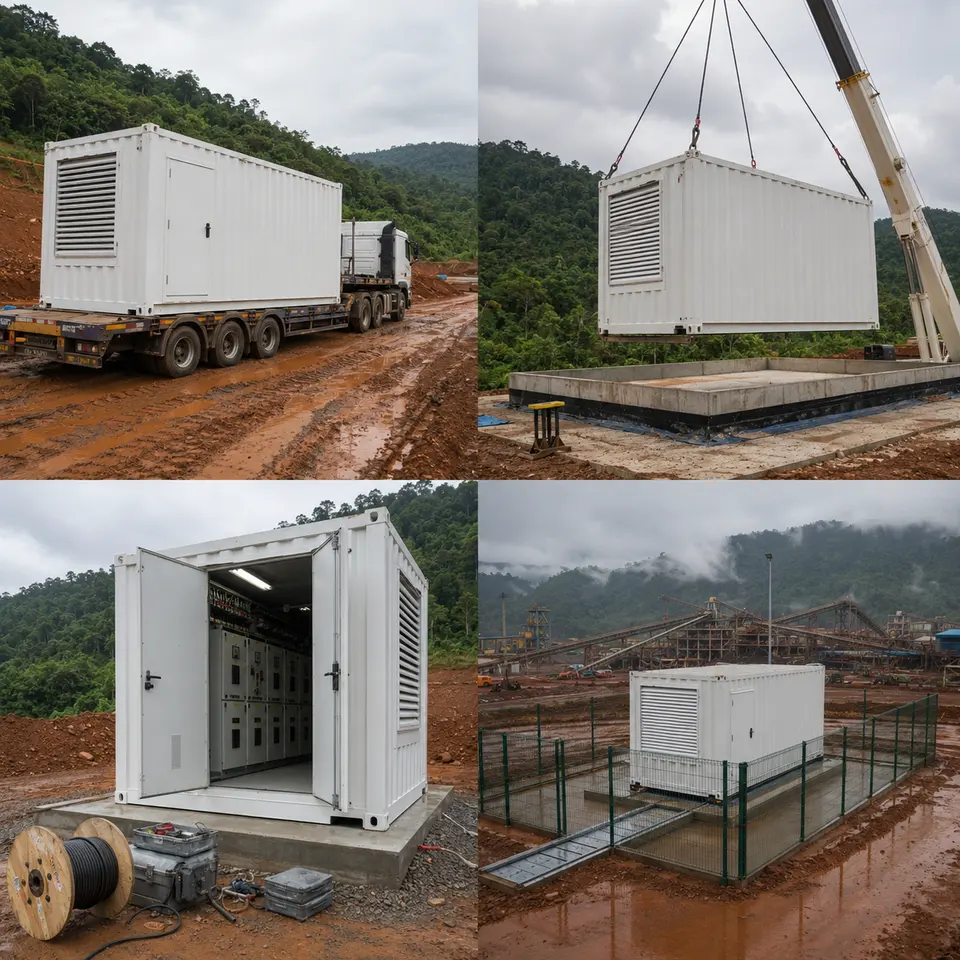
Overview
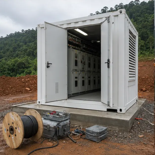
The contact sheet sets out the four stages of an installation of this type: delivery to the site, crane placement on the raised foundation, internal switchgear and cable work, and the completed installation. The sequence is dictated by access. Foundation, earth electrode and drainage are completed and proved before the container lands, because the underside becomes unreachable. Cable work follows placement so that route lengths are measured on the actual position. Functional testing that needs panels open is completed before the compound is closed and fenced. On a remote site each stage also has to be planned around the weather window, since a wet access road can suspend the whole sequence.
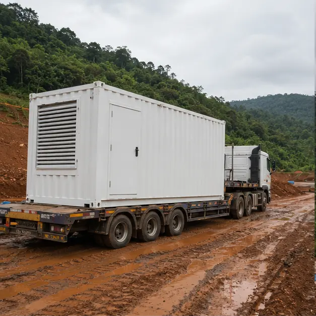
Delivery
Delivery over a wet mine access road is a transport engineering problem in its own right. Axle loading, gradient, camber, bridge and culvert capacity and turning radii are assessed before dispatch, and the unit is lashed to restrain lateral movement rather than merely held down — a container substation is tall relative to its base and its mass is concentrated low and off-centre where the transformer sits. On arrival the enclosure is inspected for transport damage, door and louvre alignment, seal condition and any water ingress, and internal equipment is checked for shifted fixings. Where an oil-immersed transformer is fitted, oil level and gasketed joints are inspected before the unit is accepted.
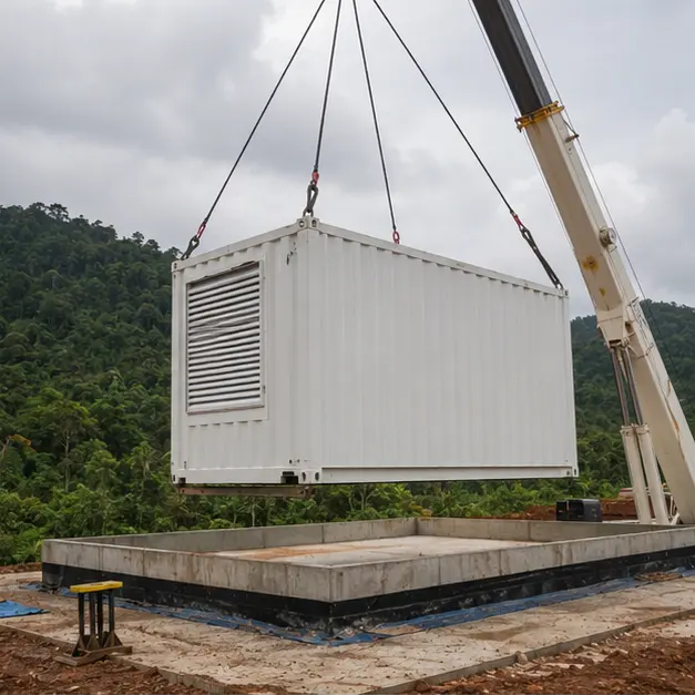
Placement
Placement onto the raised foundation is the critical lift. The raised plinth is not cosmetic: it keeps cable entries and the enclosure floor above the surface water and mud that a tropical mine site generates, and it gives the trench a fall for drainage. Lifting uses the designated corner or lug points with a spreader beam so slings do not bear on the enclosure walls, and crane capacity is assessed at working radius on ground whose bearing pressure has been checked under the outriggers. The foundation is confirmed level before the unit is set down; out-of-level seating distorts door seals, compromises the IP rating and leaves standing water on the roof. Anchoring to the foundation is completed to the seismic detail rather than left as a nominal fixing.
Internal work
Internal work covers MV and LV cable termination, busbar connection and the earthing system. MV terminations are the highest-risk joints on the installation: screen cut-back length, surface cleanliness and correct stress-cone seating decide whether they survive, and in high humidity the work is best done in a controlled period rather than left part-finished overnight. Cable screens are bonded to the internal earth bar with a conductor rated for the earth-fault duty. Busbar and terminal bolts are torqued to value and marked, because contact resistance is what converts a rated joint into a hot spot. Insulation resistance is measured, interlocks are proved by operation, and the external earth electrode is connected and its resistance recorded.
Completed configuration
The completed configuration shows the container fenced, sealed and labelled. Before energisation the installation is proved as a chain: transformer ratio and vector group verified, insulation resistance recorded, earth continuity confirmed from every enclosure part back to the main bar, and protection tested end-to-end by injection so that relay, CT circuit and trip coil are proved together. Ventilation, heating and any monitoring outputs are functionally checked. Energisation is staged — transformer charged unloaded, then LV board, then load applied progressively — with particular attention to voltage dip during the first starts of the large motors, since that is the condition the impedance was chosen against.
Specification options
For a comparable mining enquiry, MARS can configure the voltage ratio and tapping range, transformer capacity, vector group and impedance against the plant’s motor starting duty, with copper or aluminium windings. The transformer can be cast-resin dry-type or oil-immersed with containment, with insulation class and temperature-rise limits set for the site ambient and any harmonic loading from drives. MV switching can be an SF6 or solid-insulated RMU or an air-insulated metal-clad panel with withdrawable breakers. LV assemblies can be supplied in the required form of separation and short-circuit withstand rating, with motor starter or drive sections. Enclosures can be specified for IP rating, ISO 12944 corrosion category and coating system, with filtered forced ventilation or air conditioning, anti-condensation heating, fire detection and seismic anchoring. Monitoring can extend to temperature, status and alarm reporting over Modbus, IEC 61850 or DNP3.
What we need to quote a comparable system
Send as many of the following as you have. Missing items are not a problem — we will ask.
- Single-line diagram of the site supply and the intended distribution arrangement
- Incoming 20 kV details, tapping range and required vector group
- Outgoing LV voltage, system earthing arrangement and the LV distribution schedule
- Transformer capacity, plant load profile and the motor schedule with starting method and largest motor rating
- Variable-speed drive content and expected harmonic spectrum
- System fault level at the point of connection, required withstand rating and clearing time
- Protection philosophy and any existing relay settings or grading study
- Site ambient temperature range, humidity, rainfall, altitude, dust type and any corrosive process exposure
- Seismic design requirement and the foundation arrangement, raised or at grade
- Enclosure IP rating, ISO 12944 corrosion category, coating specification and internal cooling method
- Communication protocol and the mine control system interface and points list
- Site access route, permissible axle loading, available crane capacity and delivery terms