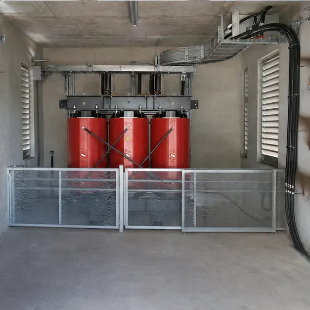
At a glance
| Country | South Africa |
|---|---|
| Application | Platinum mining and mineral-processing surface facility |
| System | 11 kV/0.4 kV cast-resin dry-type transformer, indoor installation |
| Voltage | 11 kV primary / 0.4 kV secondary |
| Frequency | 50 Hz |
| Standards basis | SANS 780 (distribution transformers) and SANS/IEC 60076-11 (dry-type transformers) with the environmental, climatic and fire classes it defines; Eskom NRS documents for the network interface, including NRS 048-2 for voltage quality limits; SANS 10142-1 for the low-voltage installation; SANS/IEC 62271-200 for the associated MV switchgear; Mine Health and Safety Act requirements for equipment in an occupied plant building |
| Visual status | Representative project visualization |
The engineering problem
A South African mining transformer is not specified against bare IEC. The buying practice is Eskom’s NRS documents and the SANS adoptions built on them, and the two are not interchangeable. SANS 780 fixes what a distribution transformer of this class must be in this market — preferred ratings, impedance, tapping arrangement, terminal and marking conventions — while NRS 048-2 sets the voltage quality limits the plant has to live inside. A unit offered as “IEC compliant” can still fail the specification it is being bought against, so the NRS and SANS references belong in the enquiry rather than in the technical query list afterwards.
The choice of cast-resin follows from where the transformer stands. This is an indoor unit in an occupied surface plant. Dry-type construction puts no insulating liquid inside the building, which removes the oil fire load, the bund, the separation distances and the containment drainage that an oil-filled unit inside a building would otherwise require. What it puts in their place is an air-cooled machine whose rating depends on the room, and that is a real constraint on the building services rather than a detail.
The load is the third driver. A concentrator’s motor duty is heavy and repetitive — mills, crushers, conveyors, pumps and fans — so starting current depresses the busbar and drive-fed loads inject harmonic current back into the windings. Both effects are decided by the plant’s motor and drive schedule, not by a rule of thumb. At 50 Hz on a system where supply voltage itself moves, the tapping range has to be chosen against the network as it actually behaves.
System configuration
| Item | Description | Specification notes |
|---|---|---|
| Transformer | 11 kV/0.4 kV three-phase cast-resin dry-type unit, indoor mounted | Vacuum-cast epoxy HV windings; climatic, environmental and fire classes selected under IEC 60076-11 for an enclosed mining plant room; capacity, impedance and tapping set against the plant motor schedule and the NRS voltage limits |
| Windings and vector group | Copper or aluminium windings, vector group matched to the LV distribution and earthing arrangement | Delta primary with earthed star secondary is the usual arrangement for a 0.4 kV plant board; impedance chosen low enough to hold volts on motor starting and high enough to keep LV fault current inside the board's withstand rating |
| Harmonic capability | Winding and core design allowance for drive-fed load | Additional eddy-current and stray loss under distorted current is accounted for by derating or by a design factor set against the measured or predicted harmonic spectrum |
| Cooling | AN natural air cooling, with AF forced-air fans where a higher rating is wanted from the same core and coil | Forced air gives a step increase in rating on the same unit; fan control is driven by winding temperature, and the room's air change rate must remove the full loss at the design ambient |
| Temperature monitoring | PT100 sensors embedded in each LV winding with an electronic temperature relay | Two-stage output — alarm and trip — plus fan start and stop; sensor placement in the hottest winding zone is what makes the reading meaningful |
| Enclosure | Optional sheet-steel protective enclosure to the required IP rating, or open unit inside a segregated transformer room | Open construction keeps convective cooling and gives clear sight of the windings for inspection; an enclosure restores touch protection and dust exclusion at the cost of rating |
| Connections | HV cable box or bare terminals; LV busbar or busduct connection to the plant board | Busbar connection avoids parallel LV cable current sharing problems; expansion joints and flexible links absorb thermal movement and stop terminal loading |
| Earthing and bonding | Core and frame earthing, enclosure bonding, connection to the plant earth grid | Conductors sized for prospective earth-fault current and clearing time; bonding continuity proved by measurement, not by inspection |
| Protection | Upstream MV protection, LV main protection, temperature trip interlock | Grading across MV, transformer and LV stages; the temperature relay trip is wired to a defined action rather than to an alarm lamp |
Installation sequence
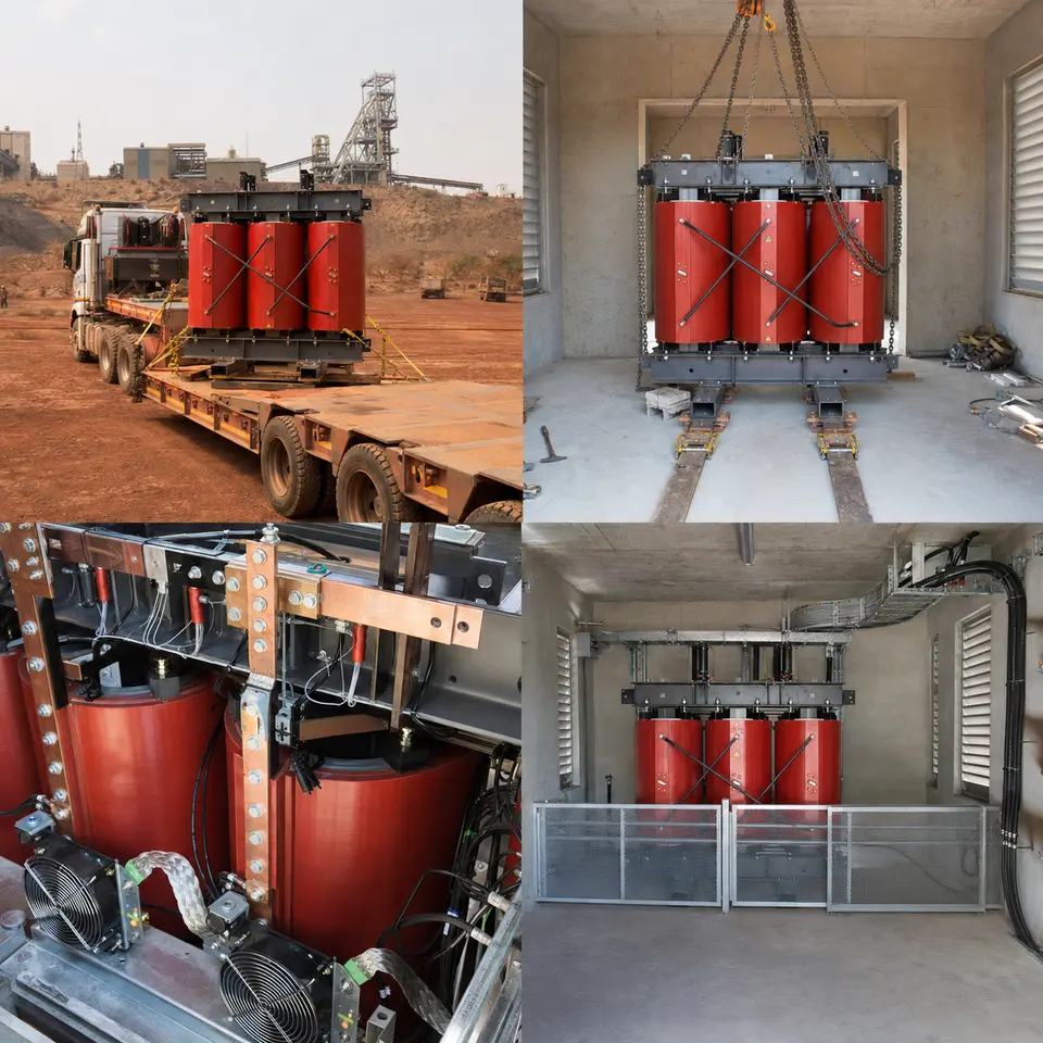
Overview
The contact sheet sets out the four stages of an installation of this type: heavy transport to site, indoor positioning with skates and lifting equipment, busbar and cooling connections, and the completed protected transformer room. The order is set by access. The room floor, plinth, cable route and earth bar are complete and proved before the unit is moved in, because the space behind and beneath a seated transformer stops being reachable. Connections are made after final position is fixed so that busbar runs and flexible links are cut to the real geometry. Ventilation and temperature protection are proved before energisation, since on a dry-type unit those are part of the rating rather than accessories.
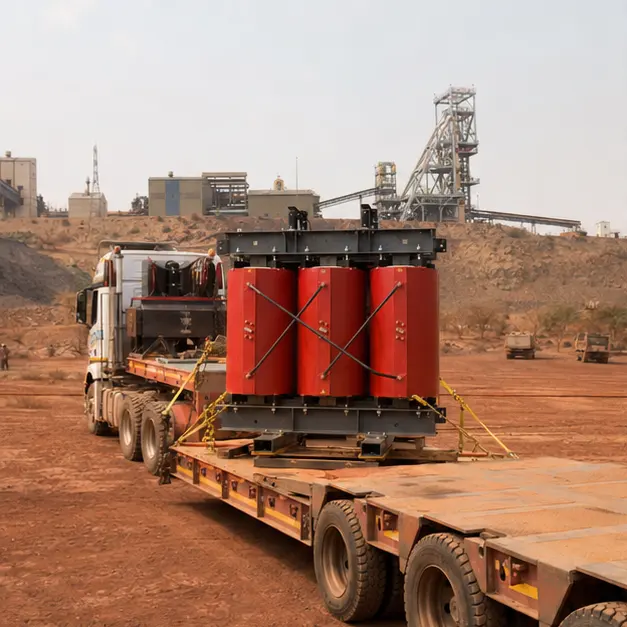
Delivery
A cast-resin unit travels as a rigid, top-heavy mass with a brittle active part. Epoxy-cast coils tolerate compression well and shock poorly, so packaging, lashing and impact recording matter more than they would for an oil-filled unit where the liquid damps movement. Route assessment covers axle loading, gradient, culvert and bridge capacity and turning radii on mine access roads. On arrival the unit is inspected before acceptance: resin surfaces checked for cracking, crazing or chipping at coil ends and spacer blocks, core clamping and winding support fixings checked for movement, terminal palms and tap links checked for distortion, and any shock indicator read and recorded. Insulation resistance is measured on receipt to give a baseline before anything is moved further.
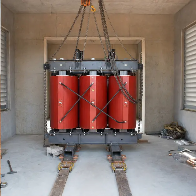
Positioning
Moving the unit into the room is done on skates or rollers rather than by repeated crane picks, because headroom indoors is usually the binding constraint. The load path is checked first: floor slab capacity along the travel route, point loading under skates, and any trench cover or duct crossing on the way. The transformer’s centre of gravity sits high and is rarely central, so pulling is done against the designated haulage points with the line of pull kept low to avoid inducing a tilt. Final positioning onto the plinth is levelled and packed, then the unit is anchored — anti-vibration mounts if fitted are set to the correct compression, since over-compressed mounts transmit the core’s 100 Hz hum straight into the building structure. Clearances to walls and to adjacent equipment are confirmed against the ventilation design, not just against the drawing.
Connection
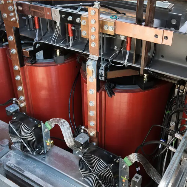
Connection work decides the long-term thermal behaviour. HV and LV joints are made with matched contact surfaces, cleaned and prepared, and torqued to value with each joint marked, because contact resistance is what turns a rated connection into a hot spot on a machine that has no oil to carry heat away. Aluminium-to-copper interfaces are made with bimetallic transition pieces rather than direct contact. Busbar and busduct runs enter through flexible links so that thermal expansion is taken by the link and not by the transformer terminal. Cooling fans, their control wiring and the PT100 temperature relay are wired and functionally proved — fan start and stop set points, alarm and trip stages, and the trip’s onward interlock. Clearance and creepage between phases and to earthed metal are checked against the built arrangement rather than assumed from the layout drawing.
Completed configuration
The completed configuration shows the transformer in a segregated, ventilated and barriered room with access control. Before energisation the installation is proved as a chain: winding insulation resistance and polarisation index recorded, turns ratio and vector group verified on every tap, winding resistance measured, and earth continuity confirmed from the core, frame, enclosure and any barrier back to the plant earth grid. Protection is proved end-to-end by injection so relay, CT circuit and trip coil are shown to work together, and the temperature relay’s trip path is proved by simulation. Energisation is staged — transformer charged unloaded, LV board next, then load applied progressively — with the first starts of the largest motors watched for voltage dip and winding temperature rise, since those are the conditions the impedance and the cooling were chosen against.
Specification options
For a comparable mining enquiry, MARS can configure the voltage ratio and tapping range, capacity, vector group and impedance against the plant’s motor starting duty and the LV board’s withstand rating, with copper or aluminium windings. Cast-resin units can be supplied to the required insulation system temperature class and temperature-rise limit, with the climatic, environmental and fire classes of IEC 60076-11 selected for an occupied plant building, and with a harmonic derating or design factor set against drive-fed load. Cooling can be natural air or forced air with fan control from winding temperature. Enclosures can be specified for IP rating, coating class and corrosion category, with anti-condensation heating where a plant room is intermittently occupied. Monitoring can extend from a two-stage temperature relay to reporting of temperature, fan status and alarms over Modbus RTU/TCP or IEC 61850. Oil-immersed alternatives with containment can be offered where the unit is sited outdoors instead.
What we need to quote a comparable system
Send as many of the following as you have. Missing items are not a problem — we will ask.
- Single-line diagram showing the 11 kV supply and the 0.4 kV distribution arrangement
- Incoming 11 kV details, required tapping range and step size, and the vector group needed
- Transformer capacity and the plant load profile, including duty cycle and load factor
- Motor schedule with the largest motor rating and its starting method, plus variable-speed drive content and expected harmonic spectrum
- System fault level at the point of connection, LV board withstand rating and required clearing time
- LV system earthing arrangement and the plant earthing study or measured earth grid data
- Applicable Eskom NRS and SANS references the equipment is being bought against, and any mine standard that overrides them
- Room dimensions, headroom, door and access route, floor loading and available ventilation or air change rate
- Site ambient temperature range, altitude, dust type and any corrosive process exposure
- Enclosure requirement — open unit in a segregated room or enclosed to a stated IP rating — with coating and corrosion class
- Protection philosophy, temperature trip interlocking requirement and communication protocol
- Delivery terms, site access route, permissible axle loading and available lifting or skating equipment