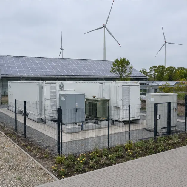
At a glance
| Country | Germany |
|---|---|
| Application | Industrial renewable-energy integration, peak shaving and grid support |
| System | 2 MWh liquid-cooled containerized battery energy storage system with PCS and transformer |
| Voltage | Battery DC bus to PCS; MV connection voltage fixed against the network operator's connection point |
| Frequency | 50 Hz |
| Standards basis | IEC 62933 series (electrical energy storage systems), IEC 62619 and IEC 63056 (industrial lithium cells and battery systems), IEC 62477-1 (power conversion), IEC 60076 series with EU Ecodesign Regulation 548/2014 as amended by 2019/1783 (Tier 2 loss limits), VDE-AR-N 4110 for medium-voltage connection, VDE-AR-E 2510-50 for stationary battery storage installations, UN 38.3 and ADR for transport |
| Visual status | Representative project visualization |
The engineering problem
A battery system connected in Germany faces a regulatory environment that is stricter and more explicit than most, and the specification has to be built around it from the start rather than adapted afterwards.
The clearest example is the transformer. Any transformer placed on the EU market must meet the Ecodesign loss limits, and since 1 July 2021 the Tier 2 levels apply. For a medium power transformer that means a defined minimum peak efficiency index, achieved through better core material, more core and winding cross-section, and consequently a larger, heavier and more expensive unit than the same rating built for a market without loss regulation. On a storage system this is not a compliance formality: the transformer sits in the round-trip efficiency path, is energised continuously, and its no-load loss is paid for every hour whether or not the battery is cycling.
The second driver is the grid connection. A storage unit connecting at medium voltage falls under VDE-AR-N 4110, which imposes generator-plant obligations — reactive power provision, voltage and frequency ride-through, active power control, defined protection settings and interface protection, and a certification chain of unit and plant certificates. Those requirements determine PCS selection and the protection scheme, so they belong in the enquiry, not in commissioning.
The third is fire protection. German expectations for stationary lithium storage cover cell-level and module-level detection, gas and smoke detection ahead of thermal runaway, deflagration venting, suppression, and separation distances from buildings and site boundaries. Liquid cooling helps here — it holds cells in a narrower temperature band and removes heat faster than forced air — but it introduces its own requirements: freeze protection through a German winter, coolant chemistry and concentration, leak detection, and pump redundancy.
System configuration
| Item | Description | Specification notes |
|---|---|---|
| Battery container | Containerized enclosure housing battery racks, thermal management, fire protection and controls | Ingress and corrosion protection specified for outdoor European exposure; deflagration venting and separation distances established at layout stage |
| Battery racks and modules | Lithium battery modules in racks with rack-level disconnection and fusing | Cells and systems to IEC 62619 and IEC 63056; module, rack and system-level monitoring of voltage, current and temperature |
| Battery management | Three-level BMS — module, rack and system — with contactor control and protection | State of charge and state of health estimation, cell balancing, and hard limits that act independently of the higher-level controller |
| Liquid cooling system | Chiller, pumps, manifolds and rack-level cold plates with a water-glycol coolant loop | Glycol concentration set for the site's minimum winter temperature; leak detection, pump redundancy and coolant flow and temperature monitoring; delta-T across racks controlled to limit cell-to-cell divergence |
| PCS | Bidirectional power conversion between the battery DC bus and the AC system | Grid-forming or grid-following as the application requires; VDE-AR-N 4110 functions — reactive capability, ride-through, active power control — provided and certified |
| Transformer | Step-up transformer between PCS output and the MV connection | Ecodesign Tier 2 loss levels; cast-resin dry-type where fire load and indoor placement govern, or oil-immersed with containment; impedance matched to the PCS |
| MV switchgear and protection | MV switching, interface protection and metering at the connection point | Protection settings and interface protection to the network operator's requirement; metering arrangement per the connection agreement |
| Fire detection and protection | Gas, smoke and heat detection, alarm, and the specified suppression or containment strategy | Detection targeted at off-gassing ahead of thermal runaway; venting, suppression and emergency shutdown interlocked with the BMS and PCS |
| Control and communication | Energy management controller with interfaces to site loads, generation and the network operator | Modbus TCP, IEC 61850 or IEC 60870-5-104; remote control and telemetry to the extent the connection agreement requires |
Installation sequence
Overview
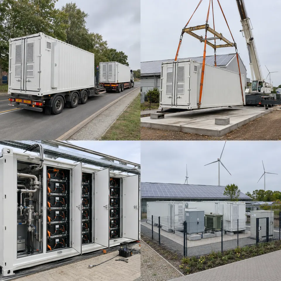
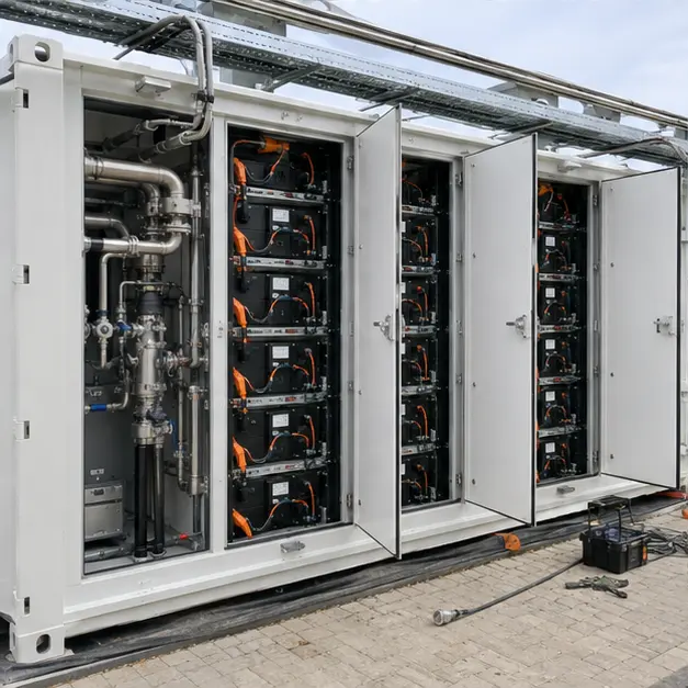
The contact sheet sets out the four stages of an installation of this type: container transport to site, crane placement on the prepared foundation, inspection of the battery racks and liquid-cooling pipework, and the completed fenced installation with PCS and transformer. The order follows what becomes inaccessible. Foundation, cable ducts, earth grid and drainage are complete and surveyed before the container lands. Cabling between container, PCS and transformer is measured on the actual positions. Coolant filling, leak testing and the first controlled charge come after mechanical and electrical work is finished, and the site is closed only once the fire detection and emergency shutdown chain has been proved.
Delivery
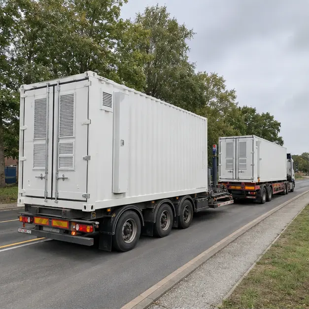
A battery container arrives as dangerous goods. Lithium modules are transported under UN 38.3 test certification and, by road in Europe, under ADR, typically at a restricted state of charge with the system electrically isolated — documentation, labelling and the transport state of charge are checked on receipt as carefully as the hardware. The route is assessed for axle loading, headroom, gradients and turning radii. On arrival the container is inspected for transport damage, seal and louvre condition, water ingress, shock-indicator status and shifted internal fixings; racks are checked for module movement and connector integrity, and the coolant circuit is inspected for damage before anything is pressurised or energised.
Placement
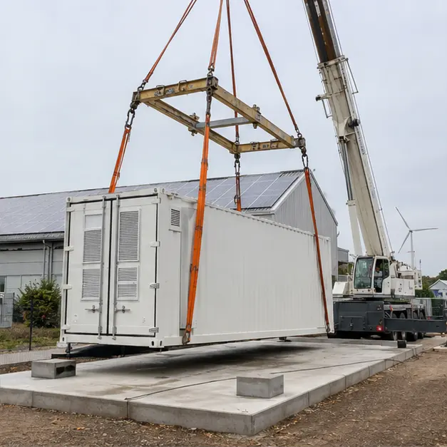
Placement is a single lift of a heavy, evenly loaded but tall unit. Lifting uses the designated corner castings or lugs with a spreader beam so slings do not bear on the container walls, doors or roof-mounted cooling equipment. Crane capacity is assessed at working radius with outrigger bearing pressure checked against the ground actually available. The foundation is confirmed level before the container is set down: liquid cooling makes level a functional requirement rather than a cosmetic one, since an out-of-level container traps air in the coolant circuit and biases flow between racks. Separation distances to buildings, boundaries and neighbouring equipment are confirmed against the fire-protection layout before anchoring is completed.
Internal work
Internal work covers DC connections, the coolant circuit and the control and safety wiring. Rack DC connections are torqued to value and marked, because a high-resistance joint on a DC bus carrying continuous current is both a loss and a fire risk, and DC arcing does not self-extinguish. Polarity, rack isolation and fuse ratings are verified before any rack is closed. The coolant circuit is filled with the specified water-glycol mixture at the concentration required for the site’s minimum temperature, then vented, pressure-tested and run to confirm flow through every rack — uneven flow shows up as cell-to-cell temperature divergence, which shortens life. Leak detection, coolant temperature and flow monitoring, and the gas, smoke and heat detection loops are functionally proved.
Completed configuration
Before energisation the installation is proved as a chain. Insulation resistance is recorded on the DC and AC sides; earth continuity is confirmed from the container, racks, PCS and transformer back to the site earth grid; transformer ratio and vector group are verified and its no-load and load loss checked against the Ecodesign declaration. Interface protection is tested end-to-end by injection, and the grid-code functions required at the connection point are demonstrated. The emergency shutdown chain is proved from every initiator — manual, gas detection, BMS fault — through to PCS shutdown and contactor opening. Commissioning then works up in stages: a controlled first charge at low power, capacity and round-trip efficiency verification, and finally the application control mode.
Specification options
For a comparable enquiry, MARS can configure energy capacity and power rating against the intended duty — peak shaving, renewable balancing or grid support — with the C-rate, cycle life and warranty basis stated for the chosen cell chemistry. Thermal management can be liquid-cooled or forced-air, with coolant chemistry and freeze protection set for the site climate. The PCS can be specified as grid-following or grid-forming, with the reactive capability, ride-through and control functions the connection requires. The transformer can be cast-resin dry-type or oil-immersed with containment, supplied to Ecodesign Tier 2 loss levels with the vector group and impedance matched to the PCS. Fire protection can be configured from detection and venting through to an active suppression system. Enclosures can be specified for IP rating, corrosion category, coating and acoustic treatment, with reporting over Modbus TCP, IEC 61850 or IEC 60870-5-104.
What we need to quote a comparable system
Send as many of the following as you have. Missing items are not a problem — we will ask.
- Single-line diagram of the site, showing generation, loads and the intended point of connection
- Required energy capacity, power rating and the duty profile — cycles per day, depth of discharge, discharge duration
- Application priority: peak shaving, self-consumption, renewable balancing, or grid services
- Connection voltage, network operator, and the applicable connection guideline and certification requirement
- Fault level at the point of connection, protection philosophy and required interface protection settings
- Reactive power, ride-through and active power control obligations at the connection point
- Site ambient temperature range, minimum winter temperature and any acoustic limits
- Fire-protection requirement, available separation distances and the local authority's expectations
- Available footprint, foundation arrangement, cable route lengths and duct positions
- Cell chemistry preference, cycle life and warranty basis required
- Communication protocol, EMS interface, points list and any existing site control system
- Site access route, permissible axle loading, available crane capacity and delivery terms