Key takeaways
- A formal microgrid definition under IEEE 2030.7 and IEC TS 62898-1 requires clearly defined electrical boundaries, co-located distributed energy resources, interconnected loads, and an autonomous control entity capable of both grid-connected and islanded operation.
- The Point of Common Coupling (PCC) serves as the primary electrical interface where medium-voltage switchgear and synchronising relays manage grid connection, intentional islanding, and black-start restoration.
- Dynamic stability in low-inertia renewable microgrids depends on grid-forming battery energy storage inverters to establish voltage and frequency reference angles within milliseconds.
- Protection schemes in microgrid power systems must incorporate directional overcurrent, rate-of-change-of-frequency (ROCOF), and adaptive relay settings to accommodate bidirectional power flows and low fault-current contributions from inverters.
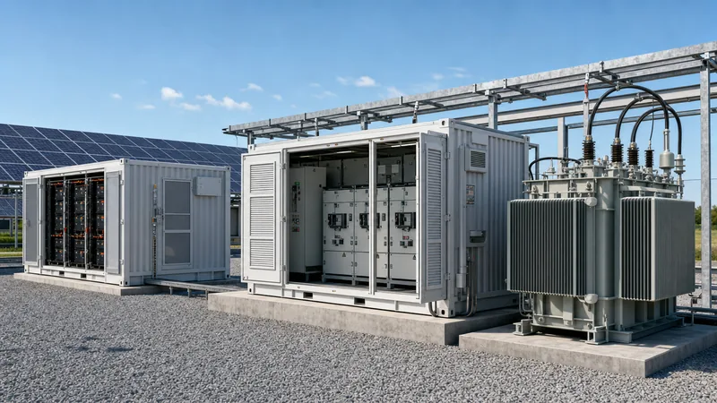
- Factory-integrated containerised substations and intelligent ring main units reduce on-site civil works and commissioning risks for industrial and commercial clean energy microgrids.
Quick answer: A formal microgrid definition describes a localised group of electricity sources and loads that normally operates connected to the traditional centralized electrical grid, but can disconnect and function autonomously in island mode as physical or economic conditions dictate. Governed by standards such as IEEE 2030.7 and IEC TS 62898-1, it relies on integrated controls, switchgear, and energy storage to ensure power quality and resilience.
Modern power distribution networks are undergoing a fundamental transition from unidirectional generation architectures toward decentralised, bidirectional networks. Industrial facilities, commercial campuses, utility distribution substations, and remote communities increasingly deploy microgrid solutions to overcome grid instability, mitigate escalating demand charges, and integrate high-penetration renewable generation. However, executing a resilient microgrid system demands precise electrical engineering across protection coordination, fast transfer switching, step-up transformation, and energy storage integration. This technical pillar guide breaks down the authoritative microgrid definition, analyses functional architectures, details critical substation interfaces, and works through sizing calculations to inform your engineering specifications.
What Is a Microgrid: Engineering Microgrid Definition and Core Criteria
According to the International Electrotechnical Commission (IEC TS 62898-1:2017, clause 3.1.1) and the Institute of Electrical and Electronics Engineers (IEEE 2030.7-2017), a microgrid is defined as a group of interconnected loads and distributed energy resources (DER) with clearly defined electrical boundaries that acts as a single controllable entity with respect to the grid.
To qualify technically as an authentic microgrid rather than a conventional standby generator arrangement or a standard distributed solar installation, a power network must satisfy four indispensable engineering criteria:
- Clearly Defined Electrical Boundary: The boundary is delineated by physical switching devices, typically housed within an intake medium-voltage (MV) switchboard or compact substation. All generation assets, energy storage units, and consumer loads reside within this defined perimeter.
- Single Controllable Entity: From the utility distribution system operator (DSO) perspective, the entire installation presents itself as a unified node. It can export power, curtail load, import scheduled active power (P), and supply reactive power (Q) via centralized or coordinated hierarchical control.
- Co-located Energy Resources: The system incorporates a combination of generation and storage assets, known collectively as power for microgrids. This includes microgrid distributed generation such as photovoltaic (PV) arrays, wind turbines, reciprocating combined heat and power (CHP) gas gen-sets, and battery energy storage systems (BESS).
- Dual Operational Capability: The system must possess the control infrastructure and fast-acting switchgear to function both when synchronised to the primary macrogrid and when operating completely detached in isolated mode.
Understanding what are microgrids also requires distinguishing between simple backup schemes and advanced microgrid energy networks. An automatic transfer switch (ATS) serving a commercial diesel generator does not constitute a microgrid; it represents an emergency standby system without continuous dynamic control, multi-source dispatch, or bidirectional power regulation. By contrast, an engineered micro power grid actively manages generation dispatch, balances local supply and demand, and optimizes power quality under all operating regimes.
How Do Microgrids Work: Operational Modes and Islanding Control
To answer how do microgrids work, engineers must evaluate how the system coordinates generation assets, power conversion systems, and protective switchgear across three distinct operational states: grid-connected mode, transition (islanding) mode, and islanded autonomous mode.
During normal grid-connected operation, the microgrid connects to the utility network at the Point of Common Coupling (PCC). The wider utility grid provides the reference frequency (e.g., 50 Hz or 60 Hz) and acts as an infinite voltage source. In this state, the local microgrid energy system executes economic dispatch algorithms. It imports power during off-peak tariff periods, discharges battery storage during peak demand windows to shave industrial peak loads, and exports surplus yield from renewable microgrids back into the utility network in compliance with IEEE 1547-2018 clause 5 interconnect limits.
The critical technical challenge occurs during the transition between operating states. When the utility network experiences an abnormal event—such as a voltage sag beyond statutory limits, an under-frequency condition, or a total blackout—the microgrid controller and high-speed protection relays must initiate an intentional islanding sequence. The transition sequence follows a deterministic switching procedure:
- The protection relay at the PCC detects an out-of-bounds parameter via instantaneous overcurrent (ANSI 50), directional power (ANSI 32), or Rate of Change of Frequency (ROCOF, ANSI 81R) tripping logic.
- The PCC circuit breaker trips open within 16 to 50 milliseconds, isolating the local network from the utility fault. Medium-voltage protection coordination protocols must prevent unintended recloser operations, as detailed in our technical analysis of electrical switchgear.
- Simultaneously, the microgrid energy storage inverter switches its operating topology from grid-following (current-source mode, relying on an external voltage vector) to grid-forming (voltage-source mode). In grid-forming mode, the inverter actively synthesises the local voltage waveform and establishes the system frequency.
- The microgrid master controller (MMC) sheds non-critical feeder loads via digital trip coils in the distribution switchboard to match total demand to available instantaneous DER capacity.
- If the microgrid operates unassisted over extended durations, black-start logic starts auxiliary synchronous generators, brings them up to synchronous speed, and uses automatic synchronisers to parallel them onto the isolated busbar.
When primary utility voltage restores and remains stable for a predetermined duration (typically 300 seconds per utility interconnection standards), the synchronising relay monitors phase angle discrepancy (typically Δθ < 10°), slip frequency (Δf < 0.1 Hz), and voltage difference (ΔV < 2%). Once parameters align, the PCC circuit breaker recloses smoothly without interrupting load power or damaging downstream rotating equipment.
Types of Microgrids: AC, DC, Hybrid, and Remote Architectures
Engineers classify types of microgrids primarily by their internal bus electrical topology and their geographic or functional grid affiliation.
From an electrical topology perspective, systems are categorised into three primary architectures:
- Alternating Current (AC) Microgrids: All DERs, storage systems, and loads connect directly to an AC distribution busbar operating at low voltage (e.g., 400 V / 480 V) or medium voltage (e.g., 11 kV, 22 kV, or 33 kV). Standard distribution switchgear, standard current transformers, and conventional step-up transformers are used throughout. However, multiple DC-to-AC and AC-to-DC conversion stages reduce overall round-trip thermodynamic efficiency.
- Direct Current (DC) Microgrids: Photovoltaic arrays, battery energy storage systems, and DC loads (such as electric vehicle fast chargers and variable speed drive DC links) couple directly to a common DC bus. This eliminates multiple conversion inverters, slashing round-trip energy losses by 4% to 8%. The technical challenge lies in DC fault clearance; DC circuit breakers require specialised arc-quenching technologies because DC current lacks a natural zero-crossing point.
- Hybrid AC/DC Microgrids: A dual-bus design where DC-native resources connect to a DC sub-grid and standard AC equipment connects to an AC distribution busbar. A bidirectional interlinking converter (BIC) manages continuous energy balancing between the two domains. This provides an optimal solution for modern industrial sites with heavy solar PV, battery storage, and variable motor loads.
The comparative matrix below outlines the performance characteristics, engineering trade-offs, and typical use cases across primary microgrid configurations:
| Architecture | Standard Bus Voltage | Conversion Efficiency | Protection Complexity | Capital Cost Profile | Primary Application |
|---|---|---|---|---|---|
| AC Grid-Tied Microgrid | 400 V / 480 V LV, 11 kV / 22 kV MV | Baseline (88% - 92% round-trip) | Moderate (standard AC relays and breakers) | Moderate (standard off-the-shelf components) | Commercial facilities, universities, industrial parks |
| Direct DC Microgrid | 380 V, 750 V, or 1500 V DC | High (93% - 96% round-trip) | High (specialised DC breakers, no zero-crossing) | High (specialised switchgear and fuses) | Data centres, EV charging hubs, telecommunication nodes |
| Hybrid AC/DC Microgrid | Dual: 750 V DC & 400 V AC | Optimised (91% - 94% round-trip) | High (coordinated cross-domain protection) | Upper-Moderate (requires BIC and dual switchboards) | Modern clean energy campuses, manufacturing hubs |
| Remote / Off-Grid Microgrid | 400 V LV up to 33 kV MV | Application-dependent | Moderate-High (low fault currents require adaptive logic) | High (requires high generation-to-load headroom) | Remote mines, island utilities, isolated rural villages |
Primary Assets in Microgrid Power Systems: Generation, BESS, and Switchgear
A robust microgrid system relies on carefully matched equipment subsystems engineered to survive electrical faults, thermal extremes, and severe transient loading. When engineering power for microgrids, designers specify four integrated hardware groups:
1. Medium-Voltage and Low-Voltage Switchgear: Switchgear forms the physical skeleton of the microgrid distribution network. The incoming intake board at the PCC must feature vacuum circuit breakers (VCB) or SF6-free gas-insulated switchgear (GIS) tested to IEC 62271-200. These assemblies house multi-function digital microgrid protection relays, synchronising check units (ANSI 25), and motorised disconnectors. For distributed campus architectures, extensible ring main units (RMUs) provide sectionalising capabilities, allowing the microgrid controller to isolate downstream faults while maintaining service to healthy feeders.
2. Battery Energy Storage Systems (BESS): In high-penetration renewable microgrids, battery storage provides critical synthetic inertia and primary frequency response. Modern installations favour Lithium Iron Phosphate (LFP) chemistry due to its superior thermal stability, long cycle life (>6,000 cycles at 80% Depth of Discharge), and non-toxic profile. To maintain system longevity and prevent thermal runaway, multi-megawatt installations employ liquid-cooled energy storage containers with closed-circuit ethylene-glycol chillers rather than forced-air HVAC units. Liquid cooling holds cell-to-cell thermal variations within ±2°C, significantly extending battery pack lifespan. Detailed containerised configurations and sizing factors are covered in our comprehensive battery storage engineering guide.
3. Step-Up and Distribution Transformers: Step-up transformers match the native output voltages of generation inverters (typically 400 V, 600 V, or 690 V) to the microgrid's internal distribution or utility interconnection voltage (ranging from 10 kV to 35 kV). These transformers face non-sinusoidal harmonic heating generated by inverter switching frequencies. Specifying transformers with appropriate K-factor ratings (e.g., K-9 or K-13) and electrostatic shielding between windings prevents high-frequency capacitive coupling. For indoor and underground substation installations, cast resin dry-type transformers eliminate fire risks, whereas outdoor pad-mounted or compact substation units utilise high-fire-point ester fluids or mineral oil complying with IEC 60076-14. Review sizing and siting criteria in our dedicated substation transformer guide.
4. Distributed Energy Resources (DERs): Photovoltaic arrays paired with industrial string or central inverters provide cost-effective active energy during daylight hours. Combined Heat and Power (CHP) gas reciprocating engines or diesel gensets provide firm synchronous capacity, black-start power, and thermal integration for industrial steam or hydronic heating circuits.
Sizing Power for Microgrids: Worked Engineering Calculation
Sizing the core generation, transformation, and storage components within an industrial microgrid power systems design requires calculating worst-case islanding duration, step-load impact, and transformer apparent power capacity.
Consider an industrial manufacturing facility with the following engineering design parameters:
- Peak active load demand ($P_{load}$): $1,800\text{ kW}$ at an uncompensated power factor ($\cos\phi$) of 0.82 lagging
- Base critical load requirement ($P_{crit}$): $950\text{ kW}$ (must remain energized continuously during utility outages)
- Required autonomous islanding endurance ($t_{island}$): $4\text{ hours}$
- On-site Rooftop Solar PV installation ($P_{pv}$): $1,200\text{ kWp}$ DC (with an AC inverter rating of $1,050\text{ kVA}$)
- Worst-case design scenario: Grid outage occurring on a heavily overcast day with Solar PV generating at only 15% rated output
- Battery chemistry: Lithium Iron Phosphate (LFP), maximum allowable Depth of Discharge ($DoD$) = 80%, round-trip system efficiency ($\eta_{sys}$) = 88%
Step 1: Calculate Total Apparent Power for Transformer Sizing
The substation step-up/interconnection transformer must carry the full peak facility load plus a 15% future expansion margin without exceeding the 65°C winding temperature rise limit (IEC 60076-2):
$$S_{load} = \frac{P_{load}}{\cos\phi} = \frac{1,800\text{ kW}}{0.82} = 2,195.12\text{ kVA}$$
Applying the 15% design headroom margin ($k_{margin} = 1.15$):
$$S_{rated} = S_{load} \times 1.15 = 2,195.12\text{ kVA} \times 1.15 = 2,524.39\text{ kVA}$$
Selecting the next standard commercial rating yields a 2,500 kVA or 3,150 kVA distribution transformer. A 3,150 kVA unit is selected to accommodate future solar expansion and prevent excessive impedance voltage drop during direct-on-line (DOL) motor starting.
Step 2: Calculate Usable and Nameplate Battery Energy Storage Capacity
Under worst-case generation conditions, the solar PV system provides:
$$P_{pv,min} = 1,050\text{ kW} \times 0.15 = 157.5\text{ kW}$$
The net unserved deficit power ($P_{net}$) that the BESS must supply continuously to sustain the critical load is:
$$P_{net} = P_{crit} - P_{pv,min} = 950\text{ kW} - 157.5\text{ kW} = 792.5\text{ kW}$$
Total usable energy ($E_{usable}$) required over the 4-hour islanding duration:
$$E_{usable} = P_{net} \times t_{island} = 792.5\text{ kW} \times 4\text{ h} = 3,170\text{ kWh}$$
Factoring in the 80% maximum Depth of Discharge limit and the 88% system round-trip efficiency (accounting for inverter, transformer, and liquid-cooling auxiliary loads):
$$E_{nameplate} = \frac{E_{usable}}{DoD \times \eta_{sys}} = \frac{3,170\text{ kWh}}{0.80 \times 0.88} = \frac{3,170}{0.704} = 4,502.84\text{ kWh}$$
The engineering team would specify a standard containerised liquid-cooled BESS rated at 4.5 MWh nameplate energy capacity, paired with a power conversion system (PCS) rated for at least $1,000\text{ kVA}$ continuous inverter output to handle starting inrush transients without voltage sag.
Microgrid Benefits and Technical Challenges in Distribution Networks
Deploying an engineered microgrid delivers substantial operational advantages, yet introduces complex system-level protection and power quality dynamics that design engineers must mitigate.
The concrete microgrid benefits include:
- Operational Resilience: Shielding critical production processes, cold-storage facilities, or healthcare facilities from utility transmission interruptions through millisecond-level seamless islanding transitions.
- Energy Cost Optimisation: Lowering utility billing through automated peak-shaving, reactive power compensation (reducing kVA demand charges), and energy arbitrage using co-located storage.
- Carbon Abatement: Enabling industrial operations to integrate up to 80% to 100% intermittent clean energy microgrids without destabilising local distribution equipment.
Conversely, microgrid engineering must address four prominent operational challenges:
- Fault Current Inversion and Suppression: Conventional electrical grids rely on synchronous generators that deliver 5 to 7 times their full-load rated current ($5-7\text{ pu}$) under short-circuit conditions, easily triggering standard magnetic trip breakers. Inverter-dominated renewable energy microgrids limit fault current to only $1.1-1.3\text{ pu}$ to protect semiconductor switches (IGBTs). This low fault contribution causes conventional inverse-time overcurrent relays (ANSI 51) to fail to trip, requiring the installation of directional overcurrent, negative-sequence overcurrent, or impedance-based distance elements.
- Bidirectional Power Flows: Legacy radial distribution networks assume power flows exclusively downstream from the substation to consumer loads. When local DER generation exceeds local demand, power flows backward through voltage regulators and step-up transformers, potentially causing reverse power trips and localized voltage swell on medium-voltage lines.
- Low System Inertia: Traditional grids feature heavy spinning rotors in power stations, which inherently resist sudden frequency variations. In low-inertia microgrids dominated by inverters, sudden motor starts or cloud transients can cause extreme frequency drop rates ($df/dt$), leading to nuisance tripping unless fast-responding grid-forming inverters are deployed.
Microgrid Substation Engineering and Interconnection Protection
The substation acts as the mission-critical gateway of any industrial or utility-interconnected microgrid, housing the primary isolation switchgear, instrumentation transformers, and coordination logic necessary to satisfy DSO technical connection requirements.
Interconnection protection engineering must strictly comply with IEEE 1547-2018 and IEC 60255 standards. The following protection functions are mandatory at the Point of Common Coupling (PCC) switchboard:
- ANSI 27 / 59 (Under/Over Voltage): Monitors phase-to-phase and phase-to-ground voltage levels, tripping the PCC breaker if the utility deviates beyond statutory operating bands for specified clearance durations.
- ANSI 81O / 81U (Over/Under Frequency): Decouples the microgrid whenever the grid frequency fluctuates outside acceptable boundaries (e.g., ±0.5 Hz from 50 Hz/60 Hz nominal).
- ANSI 81R (Rate of Change of Frequency - ROCOF): Detects sudden loss of the utility bulk supply by calculating the derivative $df/dt$, enabling rapid islanding initiation before out-of-phase auto-reclosing occurs. Typical industrial settings range from $0.5\text{ Hz/s}$ to $2.0\text{ Hz/s}$.
- ANSI 25 (Synchronism-Check): Prevents the PCC circuit breaker from closing into an unsynchronised utility supply, verifying that voltage amplitude, phase angle displacement, and frequency slip remain within strictly defined interlock limits.
- ANSI 67 / 67N (Directional Overcurrent): Differentiates between downstream internal microgrid faults and upstream external utility faults, preventing unnecessary microgrid trips during grid-side disturbances. Proper grading of these devices is explored thoroughly in our guide on transformer protection.
For modularity, reduced on-site installation schedules, and enhanced seismic performance, EPC contractors increasingly specify factory-prefabricated, containerised substations. These integrate MV switchgear, the station service transformer, DC auxiliary battery banks (110 V / 220 V DC), and digital microgrid automation controllers into a thermally insulated, weatherproof housing tested to IP54 or IP65 standards.
Microgrid Solutions Procurement: Factory RFQ Specification Checklist
When preparing a formal Request for Quotation (RFQ) for microgrid equipment packages—including substations, medium-voltage switchboards, BESS units, and step-up distribution transformers—procurement and engineering teams should provide comprehensive site and operational parameters to prevent design revisions and cost creep.
Use the following technical checklist directly within your equipment RFQ schedules:
- Point of Interconnection Characteristics: Specify utility nominal voltage (e.g., 11 kV, 13.8 kV, 22 kV, 33 kV), distribution topology (3-wire delta vs 4-wire solidly earthed wye), short-circuit level at the PCC ($I_{sc}$ in kA or short-circuit MVA), and utility protection clearing times.
- Generation & Storage Asset Breakdown: Document installed PV capacity (kWp), inverter topologies (grid-following vs grid-forming), reciprocating generator kVA ratings with subtransient reactances ($X''_d$), and BESS nameplate kWh ratings alongside continuous and peak C-rate ratings.
- Transformer Technical Specifics: Detail required rated kVA capacity, primary/secondary voltage ratings, tapping range and mechanism (e.g., ±2 × 2.5% off-circuit tap changer vs On-Load Tap Changer), vector group (e.g., Dyn11 or Dyn1), impedance voltage percentage ($Z\%$ per IEC 60076-1), cooling classification (ONAN, ONAF, or AN for dry-type), and core loss evaluation factors ($A$ and $B$ values).
- Switchgear & Substation Construction: State enclosure protection rating (e.g., IP42 indoor, IP54 outdoor), internal arc classification (IAC AFLR per IEC 62271-200, typically 25 kA / 1 s), busbar continuous current rating (A), CT/VT accuracy classes (0.2S for revenue metering, 5P20 for protection), and auxiliary control voltage (24 V, 48 V, 110 V, or 220 V DC).
- Environmental & Site Constraints: State ambient temperature extremes (minimum/maximum °C), altitude above sea level (derating applies above 1,000 m per IEC standards), seismic zone requirements, and atmospheric corrosivity category (from standard up to severe marine environments per ISO 12944).
- Communication Protocols: Identify control interface standards for microgrid controller integration (e.g., Modbus TCP, DNP3, IEC 61850 GOOSE messaging, or dry contacts for emergency hardware trips).
Next steps: specifying and sourcing
Specifying and procuring engineered assets for high-reliability microgrid power systems requires close collaboration between industrial project developers, EPC contractors, and qualified electrical equipment manufacturers. Whether your project scope requires integrated transformer substations, robust HV/LV switchgear, or high-density liquid-cooled ESS containers, our factory engineering team provides complete technical design validation, short-circuit calculations, and custom fabrication compliant with IEC and IEEE/ANSI standards.
Submit your single-line diagrams (SLD), site load profiles, and interconnection specifications to our engineering specialists to obtain a detailed technical proposal and factory direct pricing via our online quote page or by contacting our team through our contact page.
Frequently asked questions
what is a microgrid
A microgrid is a self-contained electrical distribution system comprising interconnected loads and distributed energy resources within clearly defined boundaries. Operating as a single controllable entity, it can function either synchronized to the macro utility grid or disconnected in an autonomous, islanded state.
what are microgrids
Microgrids are decentralised, localised electrical power systems that combine energy generation, battery storage, and automated controls to supply power to industrial complexes, military bases, campuses, or communities. They provide resilience against utility blackouts, reduce carbon emissions, and manage local energy costs.
how do microgrids work
Microgrids work by continuously monitoring local generation assets, battery energy storage, and facility power demand through an automated master controller. When the primary utility grid fails, high-speed switchgear disconnects at the point of common coupling, and grid-forming inverters immediately establish local voltage and frequency.
What is the difference between a microgrid and a backup generator?
A backup generator is merely an emergency asset coupled through an automatic transfer switch that operates only when utility power is lost. A microgrid operates continuously, actively balancing multiple generation sources, energy storage, and dynamic loads while optimizing power flow in both grid-tied and islanded modes.
What standards govern microgrid engineering and interconnection?
Microgrid engineering and interconnection are governed globally by IEEE 2030.7 (microgrid controller specifications), IEEE 1547-2018 (distributed energy resource interconnection), IEC TS 62898-1/2 (microgrid planning, control, and operation guidelines), and IEC 62271-200 for switchgear assembly protection.
Tags: microgrid definition microgrid solutions microgrid system renewable microgrids microgrid engineering


