Key takeaways
- Transformers are primarily categorised by voltage function (step-up versus step-down), phase count, cooling medium, and core geometry.
- The two fundamental types of transformer by functional operation are step-up transformers, which increase voltage for transmission, and step-down transformers, which reduce voltage for distribution.
- Liquid-immersed transformers offer superior cooling and dielectric strength up to 110 kV and beyond, whereas dry-type cast resin units eliminate fire hazards in indoor environments.
- Transformer core topologies dictate magnetic flux distribution and efficiency, with wound-core and shell configurations outperforming loose planar laminations.
- The least efficient type of transformer is the air-core transformer, which lacks a high-permeability ferromagnetic path and exhibits severe magnetic flux leakage.
Quick answer: The primary different types of transformers are categorised by voltage function (step-up vs step-down), dielectric insulation (liquid-immersed vs dry-type), phase construction (single-phase vs three-phase), and magnetic core architecture (core-type vs shell-type). Industrial networks select transformers based on operational duty, installation environment, rated impedance, and international efficiency mandates such as IEC 60076 and IEEE C57.12.00.
Electrical power networks rely on a diverse spectrum of transformers to bridge generation sources, high-voltage transmission backbones, and low-voltage end-use distribution systems. Specifying the wrong equipment type compromises network stability, elevates total cost of ownership through excessive no-load losses, and creates life-safety or environmental hazards. Understanding how transformers and their types operate across various voltage classes, kVA ratings, and thermal classifications is the foundational step for electrical consultants, EPC contractors, and procurement engineers designing resilient power infrastructure.
What are the two types of transformers by voltage function?
The two types of transformer classified by fundamental voltage conversion are step-up transformers and step-down transformers.
A step-up transformer increases voltage from the primary winding to the secondary winding while proportionally decreasing current according to the turns ratio equation $V_s / V_p = N_s / N_p$. These units are positioned directly at power generation facilities—such as thermal plants, hydroelectric stations, and utility-scale solar farms—elevating voltages from typical generation levels of 11 kV or 33 kV up to transmission thresholds of 110 kV, 220 kV, or 400 kV to minimise $I^2R$ copper losses over long distances. For a detailed breakdown of generator-side applications, review our step up transformer engineering guide.
Conversely, a step-down transformer reduces high transmission or medium distribution voltages to usable industrial or residential utilisation voltages. A utility distribution substation typically steps down 33 kV to 11 kV or 415 V (phase-to-phase) / 240 V (phase-to-neutral). When specifying between these 2 types of transformer, engineers must define the primary and secondary Basic Impulse Insulation Level (BIL) ratings, tap changer configuration (Off-Circuit Tap Changer vs On-Load Tap Changer), and thermal rise limits under continuous cyclic loading.
What are the 3 types of transformers by grid placement?
When examining power systems, the 3 types of transformers by grid duty are generation/step-up units, transmission/substation power transformers, and distribution transformers.
Utility infrastructure separates these assets to match operating duty cycles and fault level tolerances:
- Generator Step-Up (GSU) Transformers: Heavy-duty units running continuously near 100% capacity factor, built with reinforced structural clamping to withstand repetitive mechanical forces during high-current operations.
- Transmission Power Transformers: Substation assets operating at 66 kV to 275 kV+ with capacities from 20 MVA to several hundred MVA, linking transmission backbones and regional substations. These units require extensive monitoring systems, including on-line Dissolved Gas Analysis (DGA) and multi-stage forced cooling (ONAN/ONAF/OFAF).
- Distribution Transformers: Smaller capacity units ranging from 5 kVA single-phase pole mounts to 3,150 kVA pad-mounted or indoor transformers. These operate under variable load profiles, where minimizing core (no-load) losses is critical for meeting regional eco-design rules such as EU 548/2014 Tier 2 or US DOE 2016 standards.
Consult our 3 phase transformer guide for detailed sizing methodologies covering multi-winding configurations and vector groups.
What are 4 types of transformers classified by cooling and insulation?
The 4 types of transformers classified by cooling and dielectric medium are mineral oil-immersed, ester fluid-immersed, vacuum pressure impregnated (VPI) dry-type, and cast resin dry-type (CRDT) transformers.
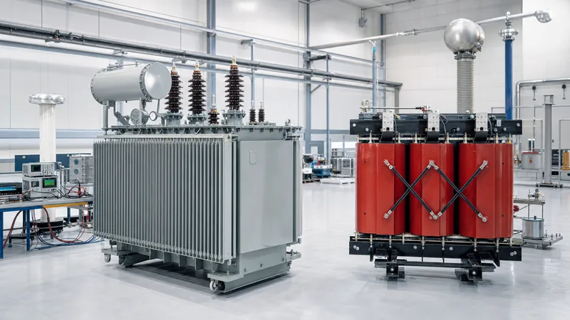
Liquid-immersed units employ a fluid medium that circulates through natural convection or forced pumping to transfer heat from the active core and coils to external radiators while providing dielectric clearance. While conventional mineral oil remains the dominant global standard under IEC 60296, synthetic and natural esters with fire points above 300 °C (K-class fluids per IEC 61039) are increasingly specified for environmentally sensitive or high-density zones. Dry-type units eliminate combustible liquids entirely, relying on ambient air cooling and Class F (155 °C) or Class H (180 °C) solid insulation systems under IEC 60076-11.
| Transformer Type | Insulation Medium | Typical Voltage / kVA Range | Cooling Class | Primary Application |
|---|---|---|---|---|
| Mineral Oil-Immersed | Mineral insulating oil | Up to 110 kV+ / 5 kVA – 100+ MVA | ONAN, ONAF, OFAF | Outdoor substations, utility grids, heavy industrial plants |
| Synthetic / Natural Ester | Bio-based or synthetic ester fluid | Up to 66 kV / 100 kVA – 40 MVA | KNAN, KNAF | Urban substations, waterways, renewable generation sites |
| Cast Resin Dry-Type | Solid epoxy resin under vacuum | Up to 36 kV / 50 kVA – 20 MVA | AN, AF | Commercial high-rises, metro tunnels, indoor switchgear rooms |
| VPI Dry-Type | Polyester/silicone varnish pressure-impregnated | Up to 15 kV / 50 kVA – 5 MVA | AN, AF | Marine vessels, clean industrial facilities, retrofit enclosures |
For an in-depth comparison of operational expenses, enclosure ingress ratings, and maintenance intervals between liquid and air-cooled units, refer to our analysis on oil-immersed vs dry-type transformers.
Types of transformer core and structural shapes
The main types of transformer core configurations are core-type, shell-type, and toroidal designs, each defined by how the magnetic flux paths surround or are surrounded by the electrical windings.
In core-type construction, the copper or aluminium windings encircle the outer vertical limbs of the laminated magnetic core. This design simplifies high-voltage coil insulation and thermal duct routing, making it the dominant architecture for medium- and high-voltage power distribution. The laminations are typically built from high-permeability, Cold-Rolled Grain-Oriented (CRGO) silicon steel stacked with step-lap joints to suppress eddy currents and minimise acoustic noise.
In shell-type construction, the magnetic core surrounds the windings on both sides. The windings are stacked in 'pancake' style discs interleaved between the core sections. This architecture offers superior mechanical bracing against short-circuit forces, frequently serving heavy industrial duty such as electric arc furnaces. Toroidal transformers utilise a continuous ring-shaped wound strip core without air gaps, producing near-zero stray magnetic fields and high volumetric efficiency, though winding complexity limits toroidal shapes primarily to instrumentation and low-power specialty applications. To inspect structural design standards in detail, see our breakdown of transformers internal components.
Specialised types of electrical transformers in modern networks
Specialised types of electrical transformers include autotransformers, instrument transformers (current and voltage transformers), and isolation transformers designed for targeted operational challenges.
Unlike multi-winding units, an autotransformer shares a single continuous winding per phase that acts simultaneously as primary and secondary via intermediate taps. When the transformation ratio is close to unity (such as stepping 275 kV down to 132 kV, or 480 V to 380 V), autotransformers dramatically reduce physical footprint, winding copper weight, and load losses compared to double-wound units, although they provide zero galvanic isolation between systems.
Instrument transformers isolate protective relays and metering systems from medium- and high-voltage circuits. Current transformers (CTs) step down high primary currents (e.g., 1000 A to standard 1 A or 5 A secondary signals), while voltage transformers (VTs) reduce kilovolt potentials down to 100 V or 110 V. Both must conform to strict accuracy classes (such as 0.2S for revenue metering or 5P20 for protection) under IEC 61869 standards.
Efficiency benchmarks: why the least efficient type of transformer is the air-core design
The least efficient type of transformer is the air-core transformer, which lacks a ferromagnetic core and suffers from severe magnetic flux leakage and negligible mutual inductance.
Without a high-permeability magnetic pathway (silicon steel cores typically exhibit relative permeability $\mu_r > 4000$, whereas air has $\mu_r \approx 1$), an air-core unit requires enormous magnetising currents to induce even modest secondary voltages. Consequently, air-core units are never used in continuous power distribution; they are restricted to high-frequency radio applications or specific transmission air-core reactors where saturation under extreme fault currents must be prevented.
In commercial power networks, modern ferromagnetic transformers achieve full-load efficiencies between 98.5% and 99.6%. Losses comprise two components:
- No-Load Losses (Iron Losses): Continuous losses resulting from magnetic hysteresis and eddy currents in the core laminations, present 24/7 whenever the transformer is energized regardless of load.
- Load Losses (Copper Losses): Variable losses driven by winding resistance ($I^2R$) and stray eddy currents in structural clamps, scaling with the square of the operating current.
How to select between different kinds of transformers
Selecting the optimal transformer configuration requires evaluating environmental constraints, electrical load profiles, safety codes, and life-cycle economics.
- Determine Installation Environment: Specify dry-type (cast resin) transformers for indoor basements, healthcare facilities, and confined commercial vaults requiring compliance with fire safety codes (IEC 60076-11 certified ratings). Specify outdoor liquid-immersed units where higher capacities, severe ambient climates (-40 °C to +50 °C), or lower initial capital expenditures govern.
- Calculate KVA Capacity and Impedance: Size the continuous rated kVA based on peak anticipated load plus growth margins, factoring in derating for harmonics (K-factor loads) per IEEE C57.110. Match short-circuit impedance percentage (%Z) to switchgear withstand ratings.
- Establish Voltage Class and Tap Requirements: Confirm primary and secondary nominal voltages, vector group arrangements (such as Dyn11 for balanced commercial four-wire distribution), and specify whether voltage volatility necessitates an automated On-Load Tap Changer (OLTC).
- Verify Total Ownership Losses: Calculate Capitalised Cost of Losses (A and B factors) evaluating core loss penalties versus copper loss penalties over a 25- to 30-year operational horizon.
Next steps: specifying and sourcing
When preparing procurement enquiries for custom power or distribution transformers, supply the full technical data schedule: nominal kVA rating, primary and secondary voltages, frequency (50 Hz or 60 Hz), vector group, target impedance percentage (%Z), ambient temperature extremes, and required testing certifications (such as routine and type tests per IEC 60076 or IEEE C57.12). For projects requiring enclosed outdoor distribution, explore our oil-immersed transformer solutions or indoor dry-type transformer systems. You can also evaluate utility-scale power transformers up to 110 kV. Submit your single-line diagrams and tender specifications to our engineering team through our transformer quotation portal to receive factory-direct engineering support and competitive project estimates.
Frequently asked questions
what are the two types of transformers
The two primary types of transformers based on basic function are step-up transformers and step-down transformers. Step-up units increase voltage while decreasing current for efficient long-distance transmission, whereas step-down units decrease voltage to safe levels for industrial, commercial, and residential use.
what are the 3 types of transformers
The three main types of transformers categorised by electrical power system placement are generation step-up transformers, transmission substation power transformers, and distribution transformers. Together, they manage the end-to-end delivery of electricity from generating plants down to end-user equipment.
what are 4 types of transformers
Four common types of transformers categorised by cooling and construction are oil-immersed transformers, cast resin dry-type transformers, autotransformers, and instrument transformers. Each is engineered for distinct dielectric requirements, fire safety envelopes, and operational duties.
what are the two kinds of transformers
When classified by physical dielectric construction, the two kinds of transformers are dry-type transformers and liquid-immersed transformers. Liquid-immersed units utilise mineral oil or synthetic ester for cooling and insulation, while dry-type units rely entirely on air circulation and solid resin encapsulation.
the least efficient type of transformer is the
The least efficient type of transformer is the air-core transformer because it lacks a high-permeability ferromagnetic core. This design results in severe magnetic flux leakage, requiring massive magnetising currents that create unviable power losses for distribution purposes.
What is the difference between core-type and shell-type transformers?
In a core-type transformer, the electrical windings surround the outer limbs of the magnetic laminated core, facilitating easier coil insulation for high voltages. In a shell-type transformer, the core surrounds and encases the electrical windings, providing superior mechanical strength against short-circuit forces.
Tags: different types of transformers types of electrical transformers kinds of transformer types of transformer core types of power transformer


