Key takeaways
- Advanced microgrid solutions integrate inverter-based distributed energy resources and synchronous assets to achieve seamless islanding under IEEE 1547-2018 clause 5.
- Transitioning between grid-connected and islanded modes causes fault currents to drop by up to 85%, requiring dual-setting or adaptive protection relays.
- Grid-forming battery inverters establish voltage and frequency within 16 to 20 milliseconds during unplanned utility disconnection events.
- A point of common coupling (PCC) requires synchronism-check relaying (ANSI 25) and fast transfer trip schemes to prevent out-of-phase reclosing.
- Properly sized medium-voltage switchgear must withstand bidirectional short-circuit levels and rapid transient recovery voltages per IEC 62271-200.
Quick answer: Advanced microgrid solutions are modular, medium-voltage electrical architectures that combine distributed energy resources, energy storage, and automated switchgear controlled by high-speed microgrid controllers. They deliver autonomous islanding, seamless resynchronisation, and dynamic power quality regulation across grid-connected and off-grid operating states.
Industrial plants, commercial campuses, and remote utility networks face growing reliability and decarbonisation demands. Conventional standby generation systems rely on open-transition automatic transfer switches that drop critical loads for several seconds during a grid outage. Modern advanced microgrid solutions resolve this shortfall by pairing grid-forming power electronics, medium-voltage (MV) distribution switchgear, and digital control schemes to maintain power continuity without service interruption. Understanding the structural layers of an advanced microgrid power system enables project engineers to specify the exact switchgear, transformer, and protection parameters needed for resilient operation.
Key Architecture of an Advanced Microgrid
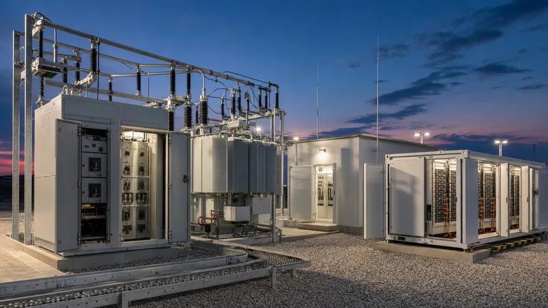
An advanced microgrid architecture consists of distributed generation sources, bidirectional energy storage, protective switchgear, and a centralised or decentralised controller interfaced at a defined medium-voltage electrical boundary. The physical installation is coordinated through five primary engineering layers:
- Point of Common Coupling (PCC): The intertie substation containing utility-grade metering, automated motorised disconnectors, and a medium-voltage circuit breaker equipped with high-speed directional and islanding protection.
- Energy Storage Systems (BESS): Utility-scale battery storage driven by grid-forming power conversion systems that provide synthetic inertia, black-start capabilities, and instantaneous voltage reference.
- Distributed Energy Resources (DERs): Photovoltaic arrays, combined heat and power (CHP) synchronous alternators, or wind generation feeding the local MV busbars.
- Switchgear and Distribution Network: Metal-clad MV switchgear panels, ring main units, and prefabricated unit substations linking generation to facility load centres.
- Microgrid Control System: High-speed industrial controllers running IEEE 2030.7-compliant dispatch algorithms that interface with a microgrid energy management system via IEC 61850 or Modbus TCP protocols.
By decoupling local frequency and voltage control from the wider grid, the facility operates as a single, controllable entity capable of balancing dynamic loads locally.
Point of Common Coupling (PCC) Switchgear and Protection
The point of common coupling requires medium-voltage switchgear capable of isolating the local network from the utility grid within three to five electrical cycles while preventing out-of-phase reclosing. Switchgear deployed at the PCC must conform to IEC 62271-200 service continuity standards (LSC2B) and maintain an adequate short-time withstand current rating (typically 25 kA or 31.5 kA for 3 seconds).
Protective relaying at the PCC includes several ANSI standard functions configured for bidirectional power flow:
- Rate of Change of Frequency (ROCOF / ANSI 81R) and Vector Shift: Detects sudden loss of the utility source within 40 to 80 milliseconds, triggering an intentional islanding sequence before utility reclosers operate.
- Synchronism Check (ANSI 25): Monitors voltage magnitude difference (ΔV < 5%), frequency slip (Δf < 0.1 Hz), and phase angle difference (Δθ < 10°) across the open breaker contacts before allowing the microgrid to parallel with the utility.
- Directional Overcurrent (ANSI 67/67N): Prevents internal microgrid faults from back-feeding the utility feeder while isolating internal generation during external faults per substation protection engineering standards.
- Under/Overvoltage (ANSI 27/59) and Under/Overfrequency (ANSI 81U/81O): Implements utility interconnection clearing curves mandated by IEEE 1547-2018 Table 1 and Table 2.
Worked Engineering Calculation: Microgrid BESS and Transformer Sizing
Sizing the power and energy ratings for an advanced microgrid requires calculating the maximum islanded load demand, step-load impact, and transformer impedance parameters. Consider an industrial facility with a peak load of 3,200 kVA (2,720 kW at 0.85 power factor) requiring a minimum autonomous runtime of 2 hours, supported by an existing 1,000 kWp rooftop solar PV installation.
To ensure system stability, the battery energy storage system (BESS) must supply 100% of the facility peak load during sudden cloud cover when operating in islanded mode:
- Continuous Inverter Inverter Rating (SBESS):
SBESS ≥ Speak × Safety Margin = 3,200 kVA × 1.15 = 3,680 kVA.
A standard 4,000 kVA grid-forming power conversion system (PCS) is selected. - Usable Energy Storage Requirement (Eusable):
Assuming minimum solar generation during a storm (PV = 0 kW) and critical base load of 2,200 kW:
Eusable = Pcritical × truntime = 2,200 kW × 2.0 h = 4,400 kWh. - Nameplate BESS Capacity (Enameplate):
Accounting for a maximum depth of discharge (DoD) of 85%, inverter efficiency of 97%, and end-of-life battery degradation factor of 80%:
Enameplate = Eusable / (DoD × ηPCS × SOH) = 4,400 kWh / (0.85 × 0.97 × 0.80) = 6,670 kWh.
Specify a 4,000 kW / 6.8 MWh LFP battery container system. - Substation Step-Up Transformer Rating (STX):
The step-up transformer connecting the 0.69 kV PCS output to the 11 kV facility distribution bus must handle full inverter output plus thermal derating per IEC 60076-1 clause 5.4:
STX ≥ SPCS / 0.95 = 4,000 kVA / 0.95 = 4,210 kVA.
A 4,500 kVA, 0.69/11 kV, Dyn11 oil-immersed or cast-resin transformer with a 6.5% short-circuit impedance (Z%) is selected.
Advanced Microgrid Solutions vs Conventional Backup Systems
A critical engineering decision when designing emergency power architecture is whether to deploy an advanced microgrid or traditional standby diesel generation paired with automatic transfer switches. The operational differences dictate switchgear layout, protection schemes, and continuous operating costs.
| Engineering Criteria | Traditional Standby Generation | Advanced Microgrid Solutions |
|---|---|---|
| Transition Time to Islanding | 10 to 60 seconds (Open transition / momentary outage) | 0 to 20 ms (Uninterrupted virtual inertia / seamless transfer) |
| Primary Voltage Source | Utility grid or Synchronous Generator | Grid-Forming Inverter or Synchronous Machine |
| Fault Current Contribution | 3.0 to 5.0 × Inominal (Sustained excitation) | 1.1 to 1.5 × Inominal (Inverter-limited) |
| Frequency Regulation | Mechanical governor droop (3-5% static droop) | Sub-cycle fast frequency response (FFR) |
| Emissions & Fuel Risk | High diesel consumption; fuel degradation risks | Zero direct emissions when charged via DERs |
| Protection Relaying Scheme | Static single-setting overcurrent relays (ANSI 50/51) | Adaptive dual-setting multi-criteria relays |
| Switchgear Specification | Standard ATS with mechanical interlocks | Arc-resistant MV switchgear with motorised vacuum breakers |
Protection Coordination Challenges: Islanded vs Grid-Tied States
Protection engineers face significant coordination difficulties because fault current magnitudes drop dramatically when a microgrid transitions from grid-connected to islanded operation. In grid-tied mode, utility sub-transmission networks contribute massive three-phase fault levels, often exceeding 20 kA to 31.5 kA on an 11 kV or 22 kV bus. Downstream overcurrent relays (ANSI 50/51) readily clear thermal overloads and short circuits within 100 milliseconds.
In islanded mode, the microgrid is primarily fed by inverter-based resources (IBRs). Grid-forming and grid-following inverters restrict short-circuit currents to between 110% and 150% of rated nominal current (In) to safeguard internal IGBT switches. Consequently, standard overcurrent elements fail to pick up, leaving faults uncleared and risking transformer damage or sustained thermal arcs.
To overcome this limitation, advanced microgrid solutions implement adaptive relaying schemes. The central microgrid controller monitors the breaker auxiliary contacts (52a/52b) at the PCC. Upon islanding, the controller transmits an IEC 61850 GOOSE message within 2 milliseconds to all feeder protection relays, instantly toggling their active configuration from Group 1 (grid-tied settings) to Group 2 (islanded settings). Group 2 uses sensitive negative-sequence overcurrent (ANSI 46), voltage-restrained overcurrent (ANSI 51V), and directional zero-sequence impedance elements to detect low-current faults reliably.
Factory Testing and Commissioning Procedure
Commissioning an advanced microgrid demands rigorous field procedures to ensure switchgear, power converters, and controllers operate safely across every operational boundary. The following sequential testing procedure validates system stability prior to commercial energisation:
- Point of Common Coupling Trip Testing: Inject secondary test currents into PCC relays to verify ANSI 27, 59, 81U, 81O, and ROCOF trip outputs. Confirm that the medium-voltage vacuum circuit breaker trips in under 60 milliseconds from trip command initiation.
- Black-Start Sequence Validation: De-energise all internal busbars completely. Issue a black-start command to the grid-forming BESS. Confirm that inverter voltage ramps from 0 to 100% within 200 milliseconds, establishing a clean 50 Hz or 60 Hz reference without exceeding inrush limits on downstream dry-type auxiliary transformers.
- Planned Seamless Islanding Test: Operate the microgrid in parallel with the utility while carrying 75% load. Issue an intentional islanding command via SCADA. Verify that the PCC breaker opens cleanly with voltage deviation remaining within ±5% and frequency remaining within ±0.2 Hz.
- Unplanned Islanding Dynamic Response: Open the upstream utility breaker without communicating an advance trip to the microgrid controller. Capture high-speed oscillography to verify that grid-forming PCS units provide sub-cycle synthetic inertia and arrest frequency decline before reaching under-frequency load shedding (UFLS) thresholds.
- Resynchronisation and Re-Paralleling: Restore utility voltage to the incoming line side of the PCC breaker. Verify that the synch-check relay (ANSI 25) monitors phase match, adjusts microgrid internal frequency and voltage, and closes the breaker smoothly when phase difference drops below 5 electrical degrees.
Next steps: specifying and sourcing
When specifying medium-voltage equipment for advanced microgrid solutions, provide your engineering team with the complete single-line diagram, prospective short-circuit fault levels, utility interconnection requirements, and generation source profiles. Specifying factory-integrated architectures simplifies site installation and testing. Review our certified medium-voltage and low-voltage switchgear engineered to IEC 62271-200, prefabricated transformer substations, and utility-scale battery energy storage systems. To receive a detailed sizing study, compliance evaluation, or commercial quote tailored to your project requirements, submit your engineering package through our online quotation request portal.
Frequently asked questions
What is an advanced microgrid solution?
An advanced microgrid solution is an integrated electrical power system that combines distributed generation, energy storage, and automated switchgear controlled by digital algorithms. It operates seamlessly either connected to the central utility grid or fully islanded, ensuring power continuity for critical infrastructure.
How does an advanced microgrid differ from a standard backup generator?
Unlike backup generators that experience an interruption of several seconds during power transfers, an advanced microgrid uses grid-forming battery inverters to transition to island mode in milliseconds without dropping load. It also integrates renewable energy sources, significantly lowering fuel costs and emissions.
What standard governs advanced microgrid interconnection?
Microgrid utility interconnection is governed primarily by IEEE 1547-2018 and IEEE 2030.7. These standards define the functional performance requirements, voltage and frequency clearing trip curves, anti-islanding detection timelines, and control specifications needed for safe grid paralleling.
Why is protection coordination difficult in an islanded microgrid?
Protection coordination is difficult because inverter-based energy resources limit short-circuit currents to approximately 1.2 to 1.5 times nominal rating, compared to 10 to 20 times nominal from utility grids. Standard overcurrent relays fail to trip, requiring adaptive dual-setting relays that switch pickup levels automatically.
What switchgear is required at the microgrid point of common coupling?
The point of common coupling requires metal-clad medium-voltage switchgear equipped with motorised vacuum circuit breakers, synchronism-check relays (ANSI 25), directional overcurrent elements (ANSI 67), and rapid anti-islanding detection relays rated for continuous bidirectional power flow and adequate short-circuit withstand capacity.
Tags: advanced microgrid solutions advanced microgrid MV switchgear microgrid protection substation engineering


