Key takeaways
- The first practical closed-core alternating current transformer was developed in 1885 by Hungarian engineers Károly Zipernowsky, Ottó Bláthy, and Miksa Déri at the Ganz factory.
- William Stanley built the first commercial, mass-producible AC distribution transformer in 1886 in Great Barrington, Massachusetts, enabling parallel grid distribution.
- Search queries asking for the first transformer frequently intersect with popular culture queries such as transformers first prime, though heavy electrical engineering roots date to 1831 induction physics.
- Modern silicon steel cores operate at 1.6 to 1.7 Tesla flux densities, cutting no-load core losses by over 80% compared to 19th-century open-core iron wire designs.
- Specifying distribution transformers today requires clear parameters under IEC 60076-1 or IEEE C57.12.00, including impedance tolerances, insulation thermal class, and guaranteed loss levels.
Quick answer: The first practical electrical transformer was co-invented in 1885 by Hungarian engineers Károly Zipernowsky, Ottó Bláthy, and Miksa Déri (the ZBD team) at the Ganz works, followed by William Stanley’s commercial parallel-circuit design in 1886. These closed-core units replaced inefficient series induction coils and established modern alternating current (AC) distribution.
For electrical engineers, procurement managers, and utility consultants, understanding who was the first transformer pioneer provides critical context for how modern AC grid architecture evolved. Today's multi-megavolt-ampere substations rely on the identical electromagnetic induction principles demonstrated in the 1880s, refined through advanced metallurgy and strict international standards. Whether evaluating grid infrastructure or addressing query ambiguities spanning fiction and industrial history, engineering specifications require empirical clarity.
Who Was the First Transformer: Historical Origins of AC Power
Determining who was the first transformer developer depends on whether one defines the device as an experimental electromagnetic induction apparatus or a practical closed-core distribution component. In 1831, Michael Faraday demonstrated the principle of mutual induction using an iron ring wrapped with two insulated copper wire coils, documented in his experimental research presented to the Royal Society. Joseph Henry independently discovered mutual induction around the same period in the United States, yet neither built an apparatus intended to transfer continuous power between separate voltage levels.
During the 1850s through 1870s, instrument makers developed induction coils, commonly known as Ruhmkorff coils. These early devices used open magnetic cores and vibrating interrupters to convert low-voltage direct current (DC) into high-voltage pulses for laboratory demonstrations and medical apparatus. They lacked continuous AC excitation and had poor energy transfer efficiency. To understand why early power distribution struggled, engineers must look to how the foundational purpose of transformer systems evolved from laboratory curiosities into continuous grid hardware capable of stepping voltages up and down without mechanical interrupters.
The 1880s Breakthrough: Gaulard, Gibbs, and the Ganz ZBD Team
The transition from experimental laboratory coils to actual alternating current distribution began in 1882 when French inventor Lucien Gaulard and English businessman John Dixon Gibbs patented their secondary generator. The Gaulard-Gibbs device featured an open magnetic circuit composed of an iron core surrounded by primary and secondary pancake coils. While Gaulard and Gibbs successfully exhibited their apparatus at the 1884 Turin Exhibition over a 40-kilometre transmission line, their system suffered from a major operational limitation: the units were connected in electrical series.
In a series circuit, switching off or altering the load on one consumer’s secondary winding altered the primary circuit current, destabilising the voltage supplied to every subsequent customer on the line. The true breakthrough arrived in 1885 at the Ganz factory in Budapest, Hungary. Three engineers—Károly Zipernowsky, Ottó Bláthy, and Miksa Déri (known collectively as the ZBD team)—recognised that transformers had to operate in parallel, connected across a constant-potential primary supply line.
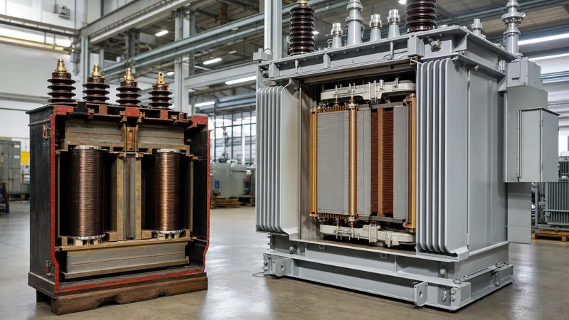
Bláthy contributed the closed toroidal magnetic circuit, preventing flux leakage and drastically cutting magnetising current. Déri conducted systematic experimentation on winding ratios to establish predictable transformation, while Zipernowsky designed the complete electrical distribution topology. The ZBD patents filed in 1885 introduced the word transformer into engineering vocabulary, producing units with closed cores composed of iron wire and achieving operational efficiencies exceeding 85%.
William Stanley and the Commercial Parallel System
While the ZBD team proved the viability of closed magnetic circuits in Europe, American electrical engineer William Stanley Jr. solved the challenge of mass manufacturability. Working for George Westinghouse, Stanley identified that the Ganz toroidal core, which required hand-threading copper coils through a continuous iron ring, was far too expensive and time-consuming for commercial deployment.
In 1885 and early 1886 in Great Barrington, Massachusetts, Stanley developed a two-piece modular core made of interlocking E-shaped and I-shaped soft iron plates. This modular construction allowed workers to pre-wind copper coils on wooden bobbins, slide them over the central core leg, and clamp the stamped laminations around them. On 20 March 1886, Stanley energised a commercial AC lighting network in Great Barrington, stepping 500 V down to 100 V to power local businesses across several blocks. Stanley’s split-core architecture forms the direct mechanical ancestor of modern laminated-core transformers, establishing how different types of transformer units are manufactured on automated assembly lines today.
Resolving Query Ambiguity: Transformers First Prime and Industrial Grid Roots
Search intent around the exact question of who was the first transformer frequently intersects with popular media terminology, specifically the query transformers first prime. In entertainment mythology, Prima represents the fictional first autonomous robotic entity created by the character Primus. This mechanical folklore often enters general search indices alongside questions about the historical origin of electrical power equipment.
In heavy industrial electrical engineering, however, prime refers exclusively to prime movers (such as steam turbines, gas turbines, or hydro generators) or primary distribution windings. The real prime transformer that enabled modern electrification is the ZBD parallel closed-core unit of 1885 and Stanley's 1886 split-lamination prototype. Recognising this semantic overlap prevents procurement professionals and researchers from conflating industrial OEM technical history with popular culture queries when searching technical equipment archives or historical patent databases such as US Patent 349,611 (Stanley's induction coil) or US Patent 373,264 (Stanley's parallel transformer).
Historical vs Modern Transformer Architecture: Technical Comparison
Comparing early 1880s equipment with contemporary distribution hardware demonstrates how fundamental electromagnetic topology has remained consistent, while material science has revolutionised efficiency, size, and dielectric endurance. The table below outlines key technical differences between early prototypes and modern industrial assets.
| Design Parameter | Gaulard-Gibbs (1882) | Ganz ZBD (1885) | Stanley Prototype (1886) | Modern IEC Distribution (Today) |
|---|---|---|---|---|
| Magnetic Circuit | Open core (straight iron bundle) | Closed core (iron wire toroid) | Closed core (E-I iron plates) | Cold-rolled grain-oriented (CRGO) steel or amorphous metal |
| Circuit Topology | Series constant-current | Parallel constant-potential | Parallel constant-potential | Parallel constant-potential (star/delta) |
| Operating Frequency | Variable (approx. 40 Hz) | Variable (approx. 40 Hz) | 133 Hz | 50 Hz or 60 Hz (±5%) |
| Insulation System | Cotton braid and varnish | Shellac and treated paper | Paper, wood, and cotton | Class A (mineral oil) / Class H/C (dry-type resin) |
| Efficiency at Rated Load | Approx. 65% to 75% | 85% to 88% | 88% to 90% | 98.5% to 99.4% (EN 50588-1 Tier 2) |
| Governing Standard | Individual inventor patents | Austro-Hungarian patent | US Patent 349,611 | IEC 60076 / IEEE C57.12.00 |
Worked Engineering Calculation: Core Loss Evolution from 1885 to Modern Steel
To appreciate the operational leap from 19th-century iron to modern cold-rolled grain-oriented (CRGO) silicon steel, consider the total core loss (no-load loss, $P_0$) calculation for an equivalent 500 kVA, 11 kV to 415 V, 50 Hz core assembly. Core loss consists primarily of hysteresis loss ($P_h$) and eddy current loss ($P_e$), described by the classical Steinmetz and Maxwell formulations:
$$P_0 = P_h + P_e = k_h \cdot f \cdot B_{max}^n + k_e \cdot f^2 \cdot t^2 \cdot B_{max}^2$$
Where $f$ is frequency (50 Hz), $B_{max}$ is peak flux density (Tesla), $t$ is lamination thickness (metres), and $k_h$, $k_e$ are material-specific coefficients.
- Input parameters for early 1886 soft iron wire core: Active core mass = 1,400 kg; operating flux density $B_{max}$ = 0.9 T; specific loss rate at 50 Hz = 4.8 W/kg. Total core loss $P_0 = 1,400 \text{ kg} \times 4.8 \text{ W/kg} = 6,720 \text{ W}$.
- Input parameters for modern CRGO (Grade 23M100, 0.23 mm thick) core: Active core mass = 950 kg; operating flux density $B_{max}$ = 1.65 T; specific loss rate at 1.7 T / 50 Hz = 0.85 W/kg per IEC 60404-8-7. Total core loss $P_0 = 950 \text{ kg} \times 0.85 \text{ W/kg} = 807.5 \text{ W}$.
- Operational impact: The modern core reduces continuous no-load losses by 5,912.5 W (an 88% reduction), saving 51,793 kWh per year in baseline thermal dissipation.
For plant engineers sizing networks, accurate calculations of no-load and load losses under 3-phase transformer configurations ensure operational compliance with regional energy directives such as EU Ecodesign or US DOE 2016 regulations.
Factory Specification Checklist: Modern Procurement Lessons from Early Inventions
Procuring distribution transformers requires capturing technical specifications in the request for quotation (RFQ) that prevent the thermal, magnetic, and mechanical failures that troubled early pioneers. Use this engineering checklist when preparing an RFQ per IEC 60076-1 or IEEE C57.12.00:
- Core Grade & Assembly: Specify domain-refined CRGO silicon steel or amorphous metal with step-lap mitered core joints (45-degree cuts) to minimise magnetic Barkhausen noise and fringing flux.
- Winding Material and Insulation: Require electrolytic copper (minimum 99.9% IACS conductivity) or EC-grade aluminium. Specify thermal insulation class per IEC 60085 (e.g., Class 105 A for oil-immersed transformers; Class 180 H or 220 C for dry-type transformers).
- Impedance (%Z): State short-circuit impedance per IEC 60076-1 Table 1 (typically 4.0% to 5.0% for ratings up to 630 kVA; 6.0% for 800 kVA to 2,500 kVA) with allowable tolerance (±10% for two-winding units).
- Cooling and Dielectric Medium: Specify cooling classification (ONAN, ONAF, AN, AF) and fluid requirements (mineral oil per IEC 60296, synthetic ester per IEC 61099, or solid cast resin).
- Vector Group and Tappings: Define primary/secondary vector relationships (e.g., Dyn11 or Ynd11) and off-circuit tap changer (OCTC) range (standard ±2 × 2.5%) or on-load tap changer (OLTC) requirements per IEC 60214-1.
- Factory Acceptance Testing (FAT): Mandate routine tests under IEC 60076-1 clause 11.1.2: winding resistance, voltage ratio, phase displacement, short-circuit impedance, load loss, no-load loss, and separate-source AC withstand voltage testing.
For more detailed drafting guidelines, consult our transformers specification engineering guide to streamline supplier technical evaluations.
Next steps: specifying and sourcing
When specifying high-efficiency distribution or substation transformers, providing precise site conditions, loss limits, and duty cycles ensures optimal manufacturing lead times and compliance. Our engineering team designs and manufactures utility-grade oil-immersed transformers, high-safety dry-type transformers, and high-capacity power transformers rated up to 110 kV, fully tested to IEC 60076 and IEEE C57 standards. To discuss short-circuit calculations, vector groups, or loss capitalisation formulas for your upcoming substation installation, send your single-line diagrams and technical schedule to our technical team via our transformer quotation portal or visit our engineering contact page for direct engineering assistance.
Frequently asked questions
who was the first transformer invented by?
The first practical transformer was invented by Hungarian engineers Károly Zipernowsky, Ottó Bláthy, and Miksa Déri at the Ganz factory in 1885. Their closed toroidal core design was followed by William Stanley’s mass-producible E-I lamination parallel transformer in 1886.
Why was the Gaulard and Gibbs secondary generator not considered practical?
The Gaulard-Gibbs secondary generator utilised an open magnetic core connected in electrical series. Turning individual loads on or off altered line current, causing unstable voltage fluctuations across all other connected loads on the network.
What is the difference between Faraday's ring and the first transformer?
Faraday’s 1831 induction ring was an experimental scientific apparatus operated by interrupting a direct-current battery circuit. The 1885 Ganz transformer operated continuously on alternating current with a closed magnetic circuit designed specifically for commercial parallel power distribution.
How does transformers first prime relate to electrical transformers?
Transformers first prime refers to fictional mythology from popular media (Prima), not electrical machinery. In electrical engineering, prime refers to mechanical prime movers driving generators or to primary high-voltage windings on electrical distribution apparatus.
What was William Stanley's contribution to the first commercial transformer?
William Stanley designed a transformer with interlocking E-shaped and I-shaped iron laminations in 1885. This allowed pre-wound copper coils to be assembled rapidly into the core, making commercial AC distribution systems commercially viable.
What core materials replaced soft iron in modern transformers?
Modern transformers replace early soft iron sheets with cold-rolled grain-oriented (CRGO) silicon steel or amorphous metal alloys. These advanced magnetic materials reduce hysteresis and eddy current losses by more than 80% at standard 50 Hz and 60 Hz operating frequencies.
Tags: who was the first transformer transformers first prime transformer history transformer engineering electrical equipment procurement