Key takeaways
- A modern transformers creator designs electromagnetic systems using finite element analysis (FEA) to balance no-load losses, stray flux, and thermal rise.
- Electrical transformer origins trace back to Michael Faraday in 1831 and the commercial closed-core alternating current transformer patent by Ganz and Company engineers in 1885.
- Industrial core construction relies on high-permeability, grain-oriented silicon steel (CRGO) or amorphous alloys cut with step-lap mitred joints to minimise hysteresis losses.
- Winding manufacturing demands precise tension control, high-conductivity electrolytic copper, and thermal-grade insulation systems tested under IEC 60076 standards.
- Vetting an equipment creator requires verifying design calculations, Factory Acceptance Test (FAT) records, and automated coil winding machinery.
Quick answer: A modern transformers creator is a specialised original equipment manufacturer (OEM) that designs, fabricates, assembles, and tests electromagnetic power conversion equipment. These manufacturers transform raw electrical steel, copper conductors, and dielectric insulation into medium- and high-voltage units built to international standards such as IEC 60076 and IEEE C57.12.00.
While pop culture associates the word with animated franchises, in utility and industrial engineering, selecting an experienced transformers creator determines the reliability, short-circuit withstand capability, and efficiency of an entire electrical grid. Whether sourcing an oil-immersed unit for a primary substation or evaluating a custom distribution asset, engineers must understand the exact metallurgical, mechanical, and dielectric processes that occur on the factory floor. Specifying power apparatus requires thorough due diligence, as detailed in our custom transformer procurement guide.
Historical Origins: Who is the Maker of Transformers in Electrical History?
The historical maker of the transformer is not a single inventor, but rather a progression of electrical physicists starting with Michael Faraday in 1831 and culminating in the ZBD team at Ganz and Company in 1885.
When examining who is the maker of transformers in practical distribution history, Faraday demonstrated mutual induction using an iron ring wrapped with two insulated coils. However, practical power distribution required an efficient closed-core topology. In 1885, Hungarian engineers Károly Zipernowsky, Ottó Bláthy, and Miksa Déri (the ZBD team) patented the first closed magnetic core transformer, establishing parallel distribution circuits. Contemporaneously, William Stanley developed the first practical alternating current (AC) step-down unit in Great Barrington, Massachusetts, in 1886. Modern manufacturers build upon these core principles, replacing rudimentary iron wire and cotton tape with laser-scribed silicon steel, Nomex insulation, and synthetic ester fluids.
The Modern Transformers Creator: Engineering Inside an OEM Plant
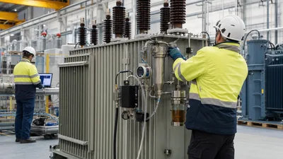
A contemporary transformers creator manages end-to-end manufacturing workflows that encompass magnetic core slitting, conductor insulation, active-part assembly, vacuum drying, tanking, and routine testing.
The engineering department models core flux density and leakage reactance using 3D finite element analysis (FEA) software. High electromagnetic forces occur during secondary terminal short circuits, generating axial and radial forces that can crush coil structures within 100 milliseconds. A competent manufacturer calculates mechanical clamping pressures precisely—typically between 3.0 MPa and 5.0 MPa—ensuring the windings remain immobile under fault currents as defined by IEC 60076-5. For three-phase assets, core-and-coil designs must align with the parameters outlined in our 3 phase transformer guide, guaranteeing system compatibility across industrial and distribution networks.
Core Design and Winding Engineering: How Creators Build Electrical Cores
Core manufacturing requires cold-rolled grain-oriented (CRGO) electrical steel or amorphous metal alloys slit to strict dimensional tolerances to suppress no-load losses.
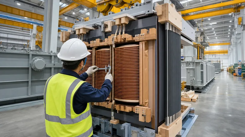
Creators use automated cut-to-length lines equipped with multi-step lap mitring machines. Step-lap joint geometries create gradual transitions between laminated steel sheets, reducing localized flux congestion, magnetostriction noise, and excitation current. The winding department then constructs the primary and secondary coils using electrolytic copper with conductivity exceeding 101% IACS (International Annealed Copper Standard). Windings for medium-voltage ratings utilise continuous disc or helical designs with radial oil ducts to facilitate convective cooling, complying with temperature rise limits specified in IEEE C57.12.00 Table 7.
Comparing Core Materials and Construction Methods
The choice of core material and winding configuration determines the operational lifecycle, capital expense, and efficiency profile of power equipment.
A knowledgeable transformers creator evaluates total ownership cost by comparing no-load core losses against load-dependent coil losses based on operational load factors. The table below compares primary materials utilized across modern fabrication facilities:
| Material / Topology | Typical Thickness (mm) | Specific Core Loss @ 1.7T, 50Hz (W/kg) | Maximum Working Flux Density (Tesla) | Primary Engineering Application |
|---|---|---|---|---|
| Conventional CRGO (standard grades) | 0.27 - 0.30 | 1.10 - 1.30 | 1.70 | Standard industrial distribution units |
| High-Permeability CRGO (Hi-B) | 0.23 - 0.27 | 0.85 - 0.95 | 1.85 | High-efficiency utility power transformers |
| Laser-Scribed CRGO | 0.20 - 0.23 | 0.65 - 0.75 | 1.90 | Substation autotransformers and primary grids |
| Amorphous Metal Alloy (Fe-Si-B) | 0.022 - 0.025 | 0.20 - 0.28 | 1.50 | Low-loss rural distribution transformers |
| Cast Resin Dry-Type Core | 0.27 - 0.30 | 1.15 - 1.35 | 1.65 | Indoor commercial and mining installations |
For installations where environmental safety prevents liquid dielectrics, consulting our dry type transformer guide provides selection criteria matching non-flammable resin systems with specific ambient conditions.
Factory Acceptance Testing: Verifying the Transformers Creator Build Quality
Factory Acceptance Testing (FAT) is the formal engineering procedure used to verify that a transformers creator has satisfied contract specifications and standard tolerances.
Procurement teams and consulting engineers must witness routine and type testing before dispatch. Tests are executed in dedicated high-voltage test bays to prevent external electromagnetic interference. The standard testing sequence includes:
- Measurement of winding resistance at ambient temperature using a four-wire Kelvin bridge per IEC 60076-1 clause 11.2.
- Voltage ratio measurement and vector group confirmation across all tap positions.
- Short-circuit impedance and load loss measurement at rated frequency and rated current.
- No-load loss and excitation current test at 100% and 110% of rated primary voltage.
- Separate-source AC withstand voltage testing (applied voltage test) to verify ground-wall insulation integrity.
- Induced overvoltage withstand test at double rated voltage and frequency to assess inter-turn insulation.
- Partial discharge (PD) measurement to ensure baseline discharge levels remain below 50 picocoulombs (pC) on high-voltage windings.
For detailed test procedures, thresholds, and calibration criteria, review our comprehensive resource on power transformer testing.
Sourcing Dilemmas: Identifying a Capable OEM Partner
Evaluating an international transformers creator requires auditing production floor infrastructure, component supply chains, and dielectric processing equipment.
Many procurement failures stem from partnering with assembly shops that outsource magnetic core cutting or lack automated vacuum pressure impregnation (VPI) and vapour-phase drying plants. A tier-one factory features clean-room winding facilities with positive air pressure to prevent metallic dust contamination. Insulation dryness must drop below 0.5% moisture content by weight before oil filling under vacuum. When specifying power transformer equipment or commercial oil-immersed distribution transformers, engineers should inspect the factory's raw material sourcing channels—especially for electrical-grade steel, solid pressboard, and de-aerated mineral oil.
Next steps: specifying and sourcing
A high-quality build begins with clear specification data. When requesting bids from a transformers creator, supply your single-line diagram, nominal primary and secondary voltages, BIL ratings, vector group, impedance range, and loss evaluation formulas ($/kW for no-load and load losses). Our team manufactures units up to 110 kV and 31.5 MVA compliant with IEC, IEEE, and GOST standards. View our power transformers and oil-immersed units, or submit your specification sheets via our quotation inquiry page for a detailed engineering proposal.
Frequently asked questions
who is the maker of transformers in power distribution?
Modern power transformers are built by original equipment manufacturers (OEMs) specializing in electrical engineering, sheet-metal fabrication, and high-voltage winding. In historical terms, the first practical alternating-current closed-core transformers were engineered in 1885 by Károly Zipernowsky, Ottó Bláthy, and Miksa Déri at Ganz and Company.
What qualifications should a commercial transformers creator possess?
A qualified transformer OEM must hold ISO 9001 quality certifications and provide third-party type test reports from accredited laboratories such as KEMA, CESI, or equivalent. They must demonstrate compliance with international manufacturing codes like IEC 60076, IEEE C57.12, or EN 50588-1.
What core materials do modern transformer creators use?
Manufacturers predominantly use cold-rolled grain-oriented (CRGO) silicon steel sheets with high magnetic permeability, graded from standard commercial to laser-treated Hi-B grades. For ultra-low-loss distribution networks, manufacturers employ amorphous metal alloys that exhibit minimal no-load hysteresis losses.
How does a transformers creator manage short-circuit forces?
A factory designs windings with balanced amp-turn distributions and clamps coils axially using pre-compressed dense pressboard rings and steel tie plates. Finite element analysis models radial and axial mechanical stress to ensure windings withstand the intense electrodynamic forces generated during downstream grid faults.
Why is vacuum drying essential in transformer manufacturing?
Vacuum drying removes moisture from solid cellulose insulation down to less than 0.5% water content by weight. Any remaining moisture accelerates insulation ageing, lowers dielectric breakdown voltage, and forms steam bubbles under operational overloads, causing catastrophic internal flashovers.
Tags: transformers creator who is the maker of transformers transformer manufacturer transformer OEM power transformer factory