Key takeaways
- Switchgear complies with UL 1558 or IEC 62271, featuring fully compartmentalised drawout power circuit breakers capable of 30-cycle short-time withstand ratings.
- Switchboards built to UL 891 or IEC 61439 use group-mounted or individually mounted molded-case or insulated-case breakers rated primarily for 3-cycle clearing times.
- Switchgear eliminates the need for instantaneous overcurrent tripping, allowing complete downstream selective coordination during upstream electrical fault events.
- A commercial switchboard offers a significantly smaller physical footprint and 25% to 40% lower capital cost than equivalent low-voltage metal-enclosed switchgear.
- Specifying front-access switchboard panels against a wall saves substation floor area, whereas switchgear mandates rear and front working clearances under NFPA 70 Article 110.26.
Quick answer: The fundamental difference in switchgear vs switchboard design lies in fault withstand capability, compartmentalisation, and breaker technology: switchgear uses individually compartmentalised, drawout power circuit breakers with a 30-cycle short-time withstand rating (UL 1558), whereas an electrical switchboard uses group-mounted or individually mounted molded-case or insulated-case circuit breakers rated for 3-cycle clearing times without mandatory short-time withstand (UL 891).
Electrical engineers, EPC contractors, and industrial facility designers regularly confront the equipment selection trade-off between a low-voltage power switching board and metal-enclosed switchgear assemblies. In North American conventions governed by the National Electrical Code (NEC/NFPA 70 Article 408) and global designs aligned with IEC 61439 low-voltage switchgear standards, selecting the incorrect equipment type impacts arc flash hazard levels, operational reliability, floor space, and capital expense. While both manage electrical distribution at 480 V, 600 V, or 690 V, their internal architecture and operational limits serve fundamentally different duty cycles.
Switchboard Definition: What Is a Switch Board?
An electrical switchboard is a large single panel, frame, or structural assembly of panels on which are mounted, on the face, back, or both, switches, overcurrent and other protective devices, buses, and usually instruments. In field engineering drawings, it is frequently abbreviated as swbd electrical apparatus. Under the classic switchboard definition established by NFPA 70 Article 100, an electrical switch board is accessible from the front or the rear and is not intended to be installed within a cabinet enclosure.
International procurement teams translating documentation—such as addressing queries like que es un switchboard—recognise that a modern distribution switchboard or commercial switchboard incorporates functional units within a rigid steel chassis. A typical switchboard assembly contains several interconnected switch board panels:
- Service entrance section: Houses the main disconnect device, revenue metering transformers, and surge protection devices.
- Distribution sections: Multi-tiered sections containing switchboard panel branches with molded-case circuit breakers (MCCBs) or fusible switches feeding downstream loads.
- Auxiliary transition bays: Interconnecting wireways, bus tie connections, and cable pull sections.
From a small house electrical switchboard or residential load centre to a massive multi-section main switch board in a high-rise facility, these assemblies act as the primary routing apparatus directing bulk power from incoming utility feeds to branch feeder circuits.
Core Difference Between Switchgear and Switchboard Assemblies
The technical difference between switchgear and switchboard configurations centres on continuous reliability, short-circuit current withstand, and mechanical isolation between adjacent components. While both assemblies direct electrical energy, their constructional philosophies reflect different risk tolerances.
A main electrical switchboard constructed to UL 891 typically integrates fixed or plug-in molded-case circuit breakers (MCCBs) or insulated-case circuit breakers (ICCBs). Busbars pass through shared horizontal chases without steel barriers separating the breaker line and load terminals from the bus compartment. Consequently, an internal arc fault in one feeder device can migrate across the internal chassis, potentially forcing an outage across the entire switchboard structure.
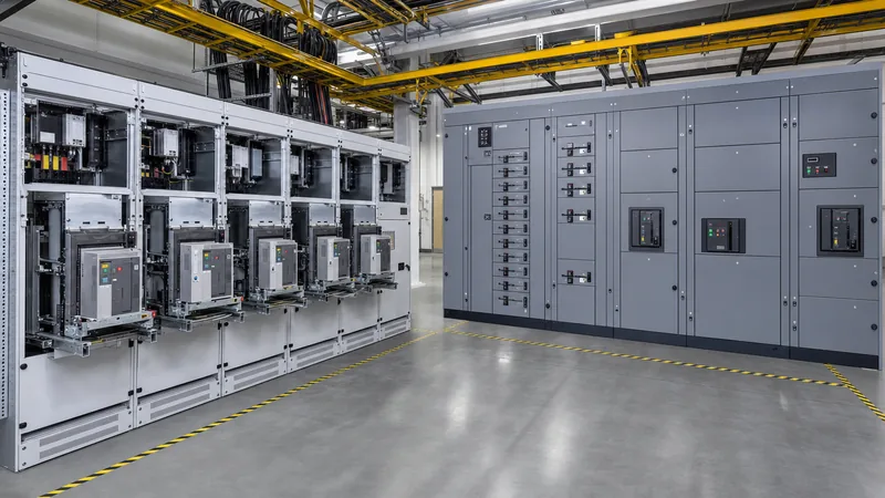
In contrast, low-voltage metal-enclosed switchgear built to IEEE C37.20.1 and UL 1558 isolates every major component into individual, grounded steel cells. The three distinct compartments are:
- Breaker compartment: Each low-voltage power circuit breaker (LVPCB) resides inside its own ventilated, sheet-metal cell with interlocked drawout racking mechanisms.
- Bus compartment: Main horizontal and vertical distribution busbars are completely segregated from the breaker and cable sections by insulating or steel barriers.
- Cable compartment: Outgoing mechanical or compression lugs are segregated from the primary bus, preventing dropped tools or vermin from initiating line-to-bus flashovers.
To explore how medium-voltage systems escalate these isolation principles, review our guide to metal-clad switchgear engineering.
Standards and Ratings: UL 1558, UL 891, and IEC Alignments
Design engineers must evaluate safety, thermal withstand, and manufacturing standards to avoid non-compliant submittals during procurement. The following comparison highlights structural and electrical distinctions governing a mains switchboard versus heavy-duty switchgear.
| Engineering Parameter | Low-Voltage Switchboard (UL 891 / NEMA PB2) | Low-Voltage Switchgear (UL 1558 / IEEE C37.20.1) | IEC Assembly Equivalent (IEC 61439-2) |
|---|---|---|---|
| Applicable Standards | UL 891, NEMA PB2, CSA C22.2 No. 244 | UL 1558, IEEE C37.20.1, ANSI C37.51 | IEC 61439-2 (Forms 1 to 4b) |
| Primary Breaker Type | Group-mounted MCCB or drawout ICCB | Drawout Low-Voltage Power Breaker (LVPCB) | Withdrawable or fixed air circuit breaker (ACB) |
| Short-Time Withstand | Not standard (typically relies on 3-cycle trip) | 30-cycle (0.50 s) rated; up to 85 kA - 100 kA | Short-time withstand (Icw) up to 1.00 s |
| Internal Segregation | Open construction; optional barriers | Full metal barriers between cells and buses | Form 3b or Form 4b barrier partitioning |
| Maintenance Access | Front-only or front/rear accessible | Front and rear access mandatory | Front or rear depending on Form classification |
| Relative Footprint | Baseline (compact; 600 mm to 900 mm depth) | +40% to +80% deeper (1500 mm to 2100 mm depth) | Modular (800 mm to 1200 mm depth) |
| Relative Cost Factor | 1.0x (economical baseline) | 1.35x to 1.70x switchboard baseline | 1.20x to 1.50x depending on internal Form |
As detailed in the electrical switchgear engineering guide, switchgear designs prioritize service continuity during severe system disruptions, which dictates these heavier mechanical enclosures and wider clearances.
Selective Coordination and Short-Time Withstand Worked Example
The choice between an electrical switchboard vs switchgear directly governs whether an electrical distribution system achieves true selective coordination down to zero seconds. When an upstream breaker must remain closed during downstream clearing, short-time withstand rating (STWR) becomes the controlling parameter.
Consider a 480 V industrial facility powered by a 2500 kVA transformer with 5.75% impedance (%Z). The prospective symmetrical fault current at the secondary terminals is calculated as:
I_sc = S / (sqrt(3) * V * (%Z / 100)) = 2500 kVA / (1.732 * 0.48 kV * 0.0575) = 52,284 A (52.3 kA)
Under UL 891 switchboard rules, main and feeder breakers utilise instantaneous trip elements that unlatch within 0.03 to 0.05 seconds (approx. 2 to 3 cycles) to protect the bus assembly from mechanical deformation under high magnetic stresses. If a 15 kA fault develops downstream on a 200 A branch circuit:
- In a UL 891 switchboard system without high short-time withstand, the 3200 A main breaker's instantaneous pick-up unit senses the high-magnitude fault and trips simultaneously with or ahead of the downstream branch breaker, resulting in an uncoordinated, facility-wide blackout.
- In a UL 1558 switchgear assembly, the LVPCBs lack instantaneous overrides. The main and feeder breakers possess a tested 30-cycle (0.50-second) short-time withstand rating of 65 kA. The main breaker's short-time delay is set to 0.35 seconds, allowing the downstream branch breaker to isolate the 15 kA fault in 0.04 seconds while the main switchgear remains energized throughout the event.
Facilities requiring continuous operation—such as hospitals, data centres, and process plants—mandate switchgear specifically to maintain this 30-cycle withstand window without risking catastrophic bus deformation.
Floor Space, Cable Entry, and Substation Layout Considerations
Equipment footprint and installation clearances frequently dictate whether a project can accommodate low-voltage switchgear or must adopt a more compact distribution switchboard. A commercial switchboard can be engineered for front-only access, allowing the rear sheet metal to rest directly against a substation perimeter wall with zero clearance, provided ventilation paths terminate through top exhaust louvres.
Conversely, UL 1558 switchgear mandates rear access for cable landing, breaker racking mechanism inspection, and primary bus bolting. NFPA 70 Article 110.26(A)(1) Condition 2 mandates a minimum working clearance behind the rear doors of 1.22 metres (48 inches) for nominal 480 V systems where exposed live parts face grounded surfaces. Front working clearance adds another 1.22 metres. Consequently, a standalone switchgear line-up requires a dedicated electrical room with double the usable floor area of an equivalent-capacity front-accessible switchboard.
Where high-density outdoor power is required, packaging this equipment into a prefabricated walk-in enclosure or a factory-assembled unit substation protects the switchgear or switchboard from ambient dust and temperature swings while optimizing the structural footprint.
Specification and RFQ Decision Matrix for Project Engineers
Project engineers must align electrical specifications with actual operational criticality, budget constraints, and maintenance workflows. Use the following structured checklist when assembling Request for Quotation (RFQ) documentation for a switchboard panel or switchgear project:
- Define the continuous current rating: Establish the main incoming bus size (e.g., 1200 A, 2000 A, 3200 A, 4000 A, 5000 A) based on transformer secondary full-load amps with minimum 25% growth allowance.
- Determine required short-circuit withstand: Specify available fault current from the utility study (e.g., 42 kA, 65 kA, 85 kA, 100 kA RMS symmetrical). State explicitly whether 30-cycle withstand (UL 1558) is mandatory for selective coordination.
- Select circuit breaker operation type: Decide between fixed-mount breakers (standard switchboard economy), plug-in/drawout ICCBs (intermediate switchboard availability), or drawout LVPCBs (switchgear reliability with shutters).
- Establish enclosure ingress protection and material: Specify NEMA 1 or IP31 for conditioned indoor switch rooms; NEMA 3R or IP54 for non-conditioned, outdoor, or dusty industrial locations.
- Define cable termination geometry: Clarify top versus bottom cable entry, incoming copper or aluminium bus duct transitions, and whether compression dual-hole lugs or mechanical set-screw lugs are required.
Next steps: specifying and sourcing
Selecting between an electrical switchboard and metal-enclosed switchgear requires balancing capital expenditure against long-term maintenance protocols and downtime risk. For mission-critical facilities requiring uninterrupted selective coordination, explore our engineered HV and LV switchgear solutions or integrated transformer substations to match your system fault levels. Provide your single-line diagram (SLD), continuous current requirements, fault level calculations, and spatial constraints directly to our applications engineering team via our substation equipment quote page or by reaching out to our global technical desk at [email protected] for technical submittal support.
Frequently asked questions
what is a switch board
A switchboard is an electrical distribution assembly composed of large structural panels containing overcurrent devices, switches, buses, and instrumentation. It routes electrical energy from a primary utility or generator source to smaller downstream branch panels, motor control centres, and commercial feeders.
Can a switchboard achieve full selective coordination without instantaneous trips?
Generally no, because most UL 891 switchboards utilise molded-case circuit breakers with non-defeatable instantaneous overrides. True selective coordination down to 0.5 seconds requires UL 1558 switchgear equipped with low-voltage power circuit breakers rated for 30-cycle short-time withstand.
What is the primary cost difference between switchgear and switchboard assemblies?
Low-voltage switchgear typically costs 30% to 60% more than an equivalently rated distribution switchboard. The cost premium covers individually compartmentalised steel cells, drawout racking cradles, automatic safety shutters, and heavy silver-plated copper busbar bracing.
Why does low-voltage switchgear require rear access while switchboards do not?
Switchgear isolates line-side busbars in a centre compartment and terminates branch power cables in a dedicated rear bay, requiring rear entry for installation and maintenance. Many switchboards utilise front-connected branch breakers, permitting flush-to-wall mounting.
What standard governs low-voltage switchgear versus low-voltage switchboards in North America?
In North America, low-voltage switchboards are certified under UL 891 and NEMA PB2, while low-voltage metal-enclosed power circuit breaker switchgear is certified under UL 1558, ANSI C37.51, and IEEE C37.20.1.
Tags: switchgear vs switchboard electrical switchboard swbd electrical switchboard definition distribution switchboard


