Key takeaways
- A high voltage switch isolates circuits, switches rated load currents, or clears fault conditions depending on whether it is classified as a disconnector, switch-disconnector, or circuit breaker under IEC 62271.
- Disconnectors provide galvanic isolation without interrupting load current, whereas load break switches handle normal operational loads, and circuit breakers interrupt prospective short-circuit currents up to 63 kA.
- Peak withstand current (Ip) must be sized according to IEC 62271-1 clause 6.6 using the peak factor 2.5 for 50 Hz systems or 2.6 for 60 Hz systems applied to rated short-time withstand current (Ik).
- Mechanical and electrical interlocks between disconnectors, high voltage switchgear breakers, and earthing switches are mandatory under IEC 62271-200 to prevent switching errors under load.
- Routine factory acceptance testing requires micro-ohm contact resistance measurement, power-frequency dielectric testing, and timing tests to ensure contact velocity and simultaneity.
Quick answer: A high voltage switch is a mechanical switching device engineered to close, carry, and interrupt electrical currents in medium and high-voltage power networks operating above 1,000 V AC. Depending on its design—disconnector, load break switch, or circuit breaker—it isolates de-energised plant, breaks operational load currents, or extinguishes massive short-circuit faults up to rated breaking capacities.
In electrical substations and industrial distribution architectures, a high voltage switch serves as the fundamental mechanism for controlling energy flow, isolating sections for maintenance, and safeguarding capital assets. Specifying switching apparatus within modern electrical switchgear assemblies requires balancing rated voltages, operational switching endurance, and short-time withstand current capabilities under demanding operating conditions. Industrial networks operating medium- and high-voltage feeders rely on coordinated switching topologies to maintain power reliability and worker safety.
What Is a High Voltage Switch: Classification and Operating Principles
A high voltage switch operates by physically separating conductive contacts within an insulating dielectric medium to interrupt or re-route electrical current. Under international standards such as IEC 62271-102 and IEC 62271-103, mechanical switching devices are categorised into three functional types based on their current-making and current-breaking capabilities.
First, an isolator or disconnector provides an open contact gap that creates a verified galvanic separation in a circuit, but it possesses negligible breaking capacity and must only open when the line is de-energised or carrying negligible capacitive charging current (below 0.5 A per IEC 62271-102 clause 4.106). Second, a switch-disconnector (often termed a load break switch or LBS) combines isolating properties with the ability to close against and interrupt rated continuous currents, transformer magnetising currents, and cable-charging currents under normal operating conditions. Third, high voltage switchgear breakers possess fully rated fault-breaking capability, opening automatically under short-circuit conditions triggered by protective relays.
Switching devices utilise different dielectric media to quench arcs formed during contact parting:
- Air: Operates at atmospheric pressure; widely used in outdoor air-insulated disconnectors and indoor medium-voltage switches equipped with arc chute deion plates.
- Vacuum: Utilises sealed ceramic vacuum interrupters with contact gaps between 8 mm and 20 mm; standard for distribution-level vacuum circuit breakers due to minimal contact erosion and 10,000 to 30,000 maintenance-free operations.
- Sulphur Hexafluoride (SF6): Employs pressurised electronegative gas for high dielectric withstand and arc quenching; prevalent in compact SF6 gas switchgear and transmission-class disconnectors.
- Solid Dielectric: Encapsulates vacuum bottles within cycloaliphatic epoxy resin, eliminating fluid or gas management in outdoor pole-mounted and pad-mounted apparatus.
High Voltage Switch vs High Voltage Breakers: Performance Comparison
Selecting between an isolating high voltage switch, a load break switch, and high voltage breakers depends strictly on the required switching duty, prospective fault level, and duty cycle. While a disconnector establishes visual clearance, it lacks arc-suppression chambers and will experience catastrophic flashover if opened under load.
The engineering comparison below contrasts device performance based on IEC 62271 standards for medium-voltage networks (typically 12 kV to 36 kV systems):
| Parameter | Disconnector (Isolator) | Load Break Switch (LBS) | Circuit Breaker |
|---|---|---|---|
| Applicable Standard | IEC 62271-102 | IEC 62271-103 | IEC 62271-100 |
| Continuous Current (Ir) | 630 A to 4,000 A | 630 A to 1,250 A | 630 A to 4,000 A |
| Breaking Capacity | None (negligible current only) | Rated normal current (e.g. 630 A) | Short-circuit rating (e.g. 25 kA to 50 kA) |
| Fault-Making Capacity | None (unless fault-make rated) | Rated peak making current (up to 50 kA) | Full short-circuit peak (up to 2.5/2.7 × Ik) |
| Arc Quenching Medium | Air / None | Air, SF6, or Vacuum | Vacuum or SF6 |
| Endurance Class | M0 (1,000 ops) to M2 (10,000 ops) | M1 (1,000 ops) to M2 (5,000 ops) | E2, M2 (10,000 ops), C2 (low restrike) |
| Galvanic Isolation Distance | Mandatory visible or verified gap | Mandatory if certified switch-disconnector | Requires separate disconnector in series |
Electrical Sizing: Worked Example for Switch Short-Circuit Withstand
A high voltage switch must withstand the thermal and electrodynamic stresses of prospective system fault currents until upstream protection clears the condition. Sizing requires calculating the rated short-time withstand current (Ik) and the peak withstand current (Ip) in accordance with IEC 62271-1 clause 6.5 and clause 6.6.
Consider an engineering project where a switch-disconnector is installed on a 33 kV, 50 Hz industrial intake substation busbar. The prospective three-phase symmetrical fault level is determined by network studies to be 21 kA with a fault duration clearing time of 1.0 s, and the system X/R ratio at the point of common coupling is 14.
Step 1: Determine thermal short-time withstand current (Ik)
Select the standard rated short-time withstand current equal to or exceeding the prospective fault. Standard increments per IEC 62271-1 are 16 kA, 20 kA, 25 kA, 31.5 kA, and 40 kA. The prospective level of 21 kA requires selecting an Ik rating of 25 kA with a rated duration (tk) of 3.0 s to allow sufficient grading margin for backup overcurrent protection.
Step 2: Determine peak withstand current (Ip)
The peak current represents the first asymmetric half-wave of the fault, producing peak electrodynamic forces proportional to the square of instantaneous current ($F \propto I^2$). Under IEC 62271-1 clause 6.6, for standard 50 Hz distribution systems with a standard time constant of 45 ms (equivalent to an X/R ratio of approximately 14), the peak factor is 2.5:
$$I_p = 2.5 \times I_k$$
$$I_p = 2.5 \times 25\text{ kA} = 62.5\text{ kA}_{\text{peak}}$$
If the system X/R ratio exceeds standard values (such as direct generator terminals where X/R can reach 30 to 50), the peak factor must be recalculated using the asymmetrical DC component decay equation per IEC 62271-100 Annex B, which yields peak factors up to 2.7 times Ik ($I_p = 2.7 \times 25\text{ kA} = 67.5\text{ kA}_{\text{peak}}$).
Step 3: Determine rated insulation levels
For the 33 kV system (highest voltage for equipment $U_m = 36\text{ kV}$), IEC 60076-3 and IEC 62271-1 Table 1 mandate a basic impulse insulation level (BIL) across the isolating distance of 195 kV peak, with a power-frequency withstand voltage of 80 kV RMS for 1 minute across the isolating distance (compared to 170 kV BIL and 70 kV RMS to earth and between phases).
Integration in High Voltage Switchgear and Enclosures
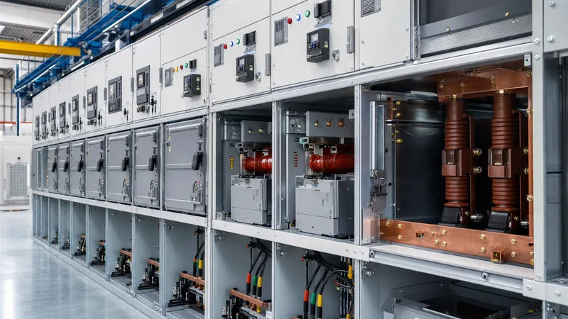
A high voltage switch is rarely installed as an isolated component; it is usually integrated inside metal-enclosed or metal-clad hv switchgear panels. Within a standard metal-clad switchgear assembly conforming to IEC 62271-200, the switch occupies a dedicated compartment segregated by earthed metallic partitions to maintain Loss of Service Continuity class LSC-2B.
In standard high tension switchgear installations, three functional switches operate within each bay:
- Busbar Disconnector: Selects the active busbar in duplicate-bus configurations and isolates the withdrawable circuit breaker truck from the live incoming busbar.
- Circuit Breaker: Provides the primary interrupting element, engineered to clear short-circuit faults and handle fast-reclose sequences (O-0.3s-CO-3min-CO per IEC 62271-100).
- Earthing Switch: Mounted on the cable-side or busbar-side to intentionally connect de-energised conductors directly to the substation earth grid, draining trapped electrostatic charges and preventing accidental re-energisation during maintenance.
Inside a compact high voltage panel, switches must meet internal arc classification (IAC) ratings, commonly specified as IAC AFLR 25 kA / 1 s or 31.5 kA / 1 s. This ensures that in the event of an internal switching failure or flashover, overpressure relief flaps route superheated ionised gases through designated exhaust channels away from operators stationed at the front, lateral, and rear boundaries.
Operating Mechanisms and Interlocking Protocols
Mechanical and electrical interlocks prevent human error during switching operations, ensuring an isolator is never operated while carrying load current. IEC 62271-200 clause 5.11 dictates that the operation of disconnectors and earthing switches must be mechanically or electro-mechanically interlocked with the corresponding circuit breaker.
To safely isolate and earth a medium-voltage feeder circuit within high voltage switchgear breakers, operators must execute the following sequential switching procedure:
- Trip the circuit breaker: Open the breaker locally or via remote SCADA control; confirm that the active phase currents on protection relays drop to zero amperes.
- Rack out or open the high voltage switch: Disengage the circuit breaker from the service position to the test/disconnected position, or open the line-side disconnector; verify the mechanical flag displays open and the contacts achieve physical clearance.
- Confirm line de-energisation: Check the capacitive voltage detecting system (CVDS / VPIS per IEC 61958) on the high voltage panel fascia to verify that zero voltage exists on all three line phases.
- Close the earthing switch: Unlatch the earth-switch mechanical interlock defeat mechanism and drive the earth switch closed; the contact mechanism must possess rated fault-making capacity (snap-action spring mechanism per IEC 62271-102) in the event the line was mistakenly live.
- Apply physical padlocks: Lock the earth switch in the closed position, affix warning tags, and apply a mechanical lock to the disconnector drive mechanism to prevent unauthorised racking.
Factory Acceptance Checklist for High Voltage Breaker Solutions
Rigorous quality control and factory acceptance testing (FAT) verify that high voltage breaker solutions and load switches meet performance parameters before dispatch to site. Field failures commonly trace back to contact misalignment during transport, dry drive linkages, or compromised dielectric seals.
Consultants and commissioning engineers should inspect the following technical parameters during factory witness tests, referencing standard tolerances:
| Inspection Item | Reference Standard | Test Methodology | Acceptance Criteria |
|---|---|---|---|
| Main Circuit Contact Resistance | IEC 62271-1 Cl. 6.4 | 4-wire Kelvin DC micro-ohmmeter at 100 A DC minimum | Values within 20% of type-test benchmark (typically < 35 μΩ per phase) |
| Dielectric Withstand | IEC 62271-1 Cl. 6.2 | Power frequency dry AC withstand voltage for 60 s | Zero flashover, disruptive discharge, or leakage current spike at rated test voltage |
| Mechanical Timing & Simultaneity | IEC 62271-100 Cl. 6.101 | Digital circuit breaker dynamic timing analyser | Phase contact discrepancy < 2.0 ms for opening, < 3.0 ms for closing; no contact bounce > 2 ms |
| SF6 Moisture & Leakage (if gas) | IEC 62271-203 | Infrared photoacoustic sensor / dew point hygrometer | Leakage < 0.5% per annum; moisture content < 150 ppmv at rated filling pressure |
| Interlock Verification | IEC 62271-200 Cl. 5.11 | Physical and electrical attempt to operate out of sequence | 100% positive block; breaker cannot close when switch is in intermediate position |
| Control Circuit Insulation | IEC 62271-1 Cl. 6.10 | 500 V / 1,000 V DC Megger on auxiliary circuits | Insulation resistance > 100 MΩ to earth |
Next steps: specifying and sourcing
When specifying a high voltage switch or procuring comprehensive high voltage switchgear products, preparing complete technical schedules accelerates pricing and engineering submittals. Engineering schedules should detail system nominal and maximum voltage, rated frequency, continuous busbar current, prospective symmetrical short-circuit current with clearing duration, BIL, IAC ratings, and preferred mechanism control voltages (110 V / 220 V DC).
Review our factory-built HV and LV switchgear assemblies and integrated prefabricated transformer substations for standard configurations, or forward your single-line diagrams (SLD) and tender specifications directly through our engineering contact page to request a formal quotation.
Frequently asked questions
What is the difference between a high voltage switch and a circuit breaker?
A high voltage switch or disconnector is designed primarily to break normal operational currents or provide galvanic isolation when de-energised. A circuit breaker incorporates advanced arc-extinguishing chambers to interrupt severe short-circuit currents up to tens of thousands of amperes automatically.
What is the role of an earthing switch in high voltage switchgear?
An earthing switch deliberately connects isolated busbars or outgoing cables to the station grounding system. It drains dangerous residual capacitive charges and prevents electric shock to maintenance personnel if an isolated feeder is inadvertently energised.
Can a high voltage disconnect switch break load current?
Standard high voltage disconnect switches cannot break load current because they lack arc-quenching media and deionising chambers. Opening an isolator while current flows produces an sustained atmospheric arc that damages equipment and presents severe arc-flash risks.
What standards govern high voltage switch design and testing?
Primary international standards include IEC 62271-102 for alternating current disconnectors and earthing switches, IEC 62271-103 for switches above 1 kV up to 52 kV, IEC 62271-100 for circuit breakers, and IEEE C37.20.2 for metal-clad switchgear assemblies.
How often should high voltage switches undergo maintenance?
Routine visual inspection and thermal imaging should occur every 6 to 12 months, with comprehensive mechanical servicing and contact resistance testing every 3 to 5 years. Severe operating environments or high switching frequencies require accelerated intervals per manufacturer instructions.
Tags: high voltage switch high voltage switchgear hv switchgear high voltage breakers high tension switchgear


