Key takeaways
- Custom switchgear resolves physical footprint limitations, non-standard bus configurations, and elevated fault duties that standard catalog units cannot accommodate.
- Busbar mechanical bracing must be designed according to IEC 60865-1 to withstand peak electrodynamic forces exceeding 15 kN/m under high short-circuit conditions.
- Specifying Form 4b internal separation under IEC 61439-2 isolates busbars, functional units, and terminals to ensure maximum service continuity during maintenance.
- Close technical alignment with custom switchgear manufacturers early in the front-end engineering design prevents costly on-site structural and civil alterations.
- Comprehensive Factory Acceptance Testing (FAT) with primary injection, contact resistance (Ductor) tests, and insulation resistance verifications reduces on-site commissioning time by up to 40%.
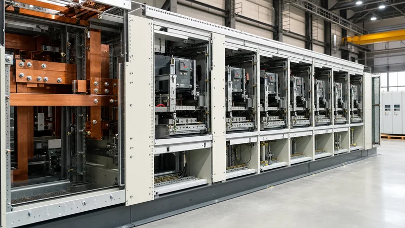
Quick answer: Custom switchgear refers to factory-engineered medium-voltage (MV) and low-voltage (LV) electrical distribution assemblies tailored to non-standard dimensions, abnormal electrical ratings, specialised protection topologies, or harsh operating environments. Unlike catalogued modular lineups, bespoke designs adapt busbar geometries, compartment segregations, and control schemes to fit existing site substations without compromising compliance with IEC 62271-200 or IEC 61439-2.
Standard production switchgear satisfies routine greenfield installations where substation civil dimensions, cable trench routes, and operational loads conform to uniform parameters. However, heavy industrial sites, marine vessels, legacy retrofit projects, and high-density data centres frequently introduce constraints that catalogue gear cannot meet. Dimensional clashes, mismatched throat connections to existing transformers, requirements for front-access-only cabling, and fault withstand ratings exceeding typical 50 kA thresholds demand bespoke mechanical and electrical engineering.
Opting for custom-built distribution assemblies enables EPC contractors and plant engineers to match busbar ratings, circuit breaker configurations, and digital relay interfaces precisely to operational demands. As detailed in our guide to MV and LV switchgear systems, matching equipment construction directly to the load profile eliminates operational compromises, reduces civil modification expenditures, and extends plant service life.
When Standard Equipment Fails: Technical Drivers for Custom Switchgear
Standard switchgear assemblies fail to deliver when physical footprint limitations, non-standard bus transitions, or severe environmental classifications make off-the-shelf enclosures unviable. In brownfield utility or industrial substations, expanding capacity often requires fitting a 36 kV or 12 kV lineup into a legacy switchroom where ceiling clearances, door widths, or floor plinth dimensions are fixed. Standard modular cubicles often require 1200 mm to 1500 mm rear clearance for cable termination and maintenance, whereas custom designs can integrate full front-access cabling, integrated top-entry bus ducts, or reduced-width breaker compartments.
Beyond physical space, non-standard system integration frequently demands custom layouts. Dual-source automatic transfer systems with mechanical and electrical interlocking, hybrid configurations housing both medium-voltage vacuum contactors and high-capacity breakers within a unified bus run, and split-bus topologies requiring specialised tie-ducts cannot be sourced from catalogue drawings. For projects involving unique distribution layouts, such as those covered in our review of switchgear breaker selection and ratings, tailor-made enclosures ensure that all mechanical interlocks comply strictly with IEEE C37.20.2 or IEC 62271-200 clause 6.106.
Environmental severity represents a third critical driver. Standard sheet-steel enclosures rated for IP31 or NEMA 1 environments deteriorate rapidly in chemical processing facilities, offshore platforms, or high-humidity desert regions. Tailored solutions incorporate grade 316L stainless steel enclosures, IP54 or IP65 sealing with specialised internal labyrinth ventilation, anti-condensation space heaters dynamically managed via dew-point sensors, and tropicalised internal insulation materials.
Custom Switchgear Switchboards vs Standard Distribution Gear
Custom switchgear switchboards differ from standard distribution gear primarily through their structural segmentation, higher internal form of separation, and heavy-duty busbar construction. While standard commercial switchboards rely on shared open chaseways and basic dead-front barriers, custom switchgear switchboards utilise fully segregated compartments for busbars, incoming and outgoing devices, and cable connections, corresponding to Form 4b (IEC 61439-2) or fully metal-clad construction (IEEE C37.20.2).
The distinction between switchgear and switchboards involves trade-offs in short-time withstand current ($I_{cw}$), compartmentation, and testing protocols. For an in-depth breakdown of these structural definitions, consult our analysis on switchgear vs switchboards. Standard switchboards often employ moulded-case circuit breakers (MCCBs) mounted on a common chassis without individual phase isolation. In contrast, heavy-duty custom assemblies incorporate drawout air circuit breakers (ACBs) or vacuum circuit breakers (VCBs), isolated shutter assemblies, and compartmentalised current and voltage transformers to permit work on de-energised sections while adjacent cubicles remain live.
The table below highlights the technical differences between mass-produced standard equipment and custom-engineered switchgear switchboards:
| Engineering Parameter | Catalogue / Standard Switchgear | Custom Switchgear Switchboards |
|---|---|---|
| Enclosure Footprint | Fixed modular dimensions (e.g., 600/800/1000 mm widths) | Millimetre-adjusted widths, depths, and heights for site fit |
| Internal Segregation | Typically Form 1 to Form 2b (IEC 61439-2) | Form 3b, 4a, or 4b with rigid phase segregation |
| Busbar Geometry | Standard single three-phase horizontal bus run | Dual-bus, U-shaped, split-level, or wrap-around configurations |
| Short-Time Withstand ($I_{cw}$) | Standard ratings: 25 kA / 35 kA / 50 kA for 1.0 s | Up to 100 kA for 1.0 s or 3.0 s with bespoke bracing |
| Cable Entry Alignment | Predetermined bottom or top entry locations | Configurable multi-angle, top-duct, side-cable, or vault entry |
| Protection & Control | Standard vendor-defined protection relays | Multi-vendor relay integration, arc flash optical sensors, synch-check |
| Corrosion Protection | Standard powder-coated mild steel (low-to-medium corrosive category) | 304/316L stainless steel, offshore marine coatings (severe marine category per ISO 12944) |
Worked Busbar Sizing and Electrodynamic Force Calculation
Bespoke busbar design in custom switchgear requires precise calculation of dynamic mechanical forces during a short-circuit fault to ensure structural supports and busbar profiles do not undergo plastic deformation under peak prospective currents ($I_p$). When switchgear must deliver a non-standard 65 kA short-circuit withstand for 1.0 second, catalogue busbar supports prove inadequate.
According to IEC 60865-1 clause 3.2, the peak electrodynamic force between parallel conductors during a three-phase short circuit is determined by the peak prospective current, conductor geometry, and centre-to-centre spacing. Consider a custom low-voltage lineup operating with an incoming prospective fault current of $I_{cw} = 65\text{ kA}$ (RMS). The peak factor ($n$) per IEC 61439-1 Table 7 for a power factor of $\cos\phi = 0.2$ is 2.2. Therefore, the peak short-circuit current is calculated as:
$$I_p = I_{cw} \times n = 65\text{ kA} \times 2.2 = 143\text{ kA}$$
Assuming a centre-to-centre phase conductor spacing ($a$) of 110 mm ($0.11\text{ m}$) and a span between busbar support insulators ($l$) of 350 mm ($0.35\text{ m}$), the maximum electromagnetic force per unit length ($F_m$) acting on the centre phase conductor is:
$$F_m = \frac{\mu_0}{2\pi} \times \frac{\sqrt{3}}{2} \times \frac{I_p^2}{a}$$
Where $\mu_0 = 4\pi \times 10^{-7}\text{ H/m}$. Substituting the parameters:
$$F_m = (2 \times 10^{-7}) \times 0.866 \times \frac{(143 \times 10^3\text{ A})^2}{0.11\text{ m}} = 0.1732 \times \frac{2.0449 \times 10^{10}}{0.11} \approx 32,200\text{ N/m}$$
The total force ($F_s$) exerted on each busbar support insulator across the 0.35 m span is:
$$F_s = F_m \times l = 32,200\text{ N/m} \times 0.35\text{ m} = 11,270\text{ N} = 11.27\text{ kN}$$
Consequently, custom switchgear manufacturers must select epoxy resin or cycloaliphatic support insulators with a minimum mechanical cantilever strength rating of 12 kN (incorporating a safety margin) rather than standard commercial supports rated at only 5 kN to 7.5 kN. Furthermore, the busbars themselves—configured here using double $100\text{ mm} \times 10\text{ mm}$ E-Cu copper bars per phase—must be checked against the permissible bending stress ($\sigma_{tot} \le 0.8 \times R_{p0.2}$) per IEC 60865-1 clause 3.3 to guarantee that no permanent deflection occurs during a major fault event.
Collaborating with Custom Switchgear Manufacturers on Complex RFQs
Engaging successfully with custom switchgear manufacturers requires issuing a detailed engineering package that defines boundary conditions rather than relying on generic performance specifications. Catalogue switchgear can be ordered through simple part numbers, but tailor-made assemblies demand comprehensive Front-End Engineering Design (FEED) data to ensure mechanical and operational alignment.
Consultants and procurement teams should provide the following critical documentation when requesting tenders for custom assemblies:
- Single-Line Diagrams (SLDs) with Protection Schemes: Clear SLDs depicting nominal voltage, continuous bus currents, fault break/make capabilities, instrument transformer ratios, and relay functional codes per IEEE C37.2. Ensure compliance with requirements outlined in IEC 61439 design verification standards.
- Substation Physical Interface Constraints: Structural floor loading limits (kg/m²), ceiling height clearances, overhead travelling crane hooks, entry door dimensions, and exact locations of floor penetrations or trench openings.
- Cable and Bus Duct Terminations: Exact cable cross-sections, number of conductors per phase, single-core versus multi-core cable types, bending radius allowances, and whether gland plates require non-magnetic aluminium or brass for high currents to prevent eddy current heating.
- Control and SCADA Architecture: Auxiliary DC/AC control voltages, communication protocols (IEC 61850, Modbus TCP/IP, or Profibus), interlocking logic tables, and specific automated transfer switch (ATS) sequencing schemes.
Addressing these points early in the tender process eliminates design revisions, prevents expensive field modifications, and ensures that the factory engineering team models all bus duct transitions, cable spools, and breaker interlocks in 3D CAD software prior to structural steel fabrication.
Factory Acceptance Testing (FAT) Checklist for Bespoke Assemblies
A structured Factory Acceptance Testing (FAT) protocol validates that custom assemblies satisfy both client engineering parameters and mandatory international standards prior to dispatch. Because custom switchgear incorporates unique enclosure dimensions, busbar arrangements, and control wiring, FAT must verify mechanical clearances, thermal performance, and dynamic protection logic more comprehensively than for batch-produced modular units.
Engineers should execute and sign off on the following inspection checklist at the manufacturer's testing facility:
| Inspection & Test Item | Reference Standard | Acceptance Criteria & Engineering Tolerance |
|---|---|---|
| Dimensional & Clearance Verification | IEC 62271-1 / IEC 61439-1 | Phase-to-phase and phase-to-earth clearances verified; overall footprint within ±2 mm of approved drawings. |
| Torque Verification & Marking | Project Specification | 100% bolt torque check using calibrated torque wrenches; torque-seal paint applied to all structural and electrical joints. |
| Contact Resistance (Ductor Test) | IEC 62271-200 cl. 6.4 | Main circuit resistance across circuit breaker contacts and bus joints measured with 100 A DC; value must not exceed 1.2 × type-test benchmark. |
| Power-Frequency Withstand Voltage | IEC 62271-200 cl. 6.2 / IEC 61439-1 cl. 10.9 | Dielectric test applied for 60 seconds (e.g., 28 kV RMS for 12 kV switchgear; 2.5 kV RMS for 415 V switchgear) with zero breakdown or flashover. |
| Insulation Resistance (Megger) | IEEE C37.20.2 / IEC 61439-1 | Pre- and post-dielectric test insulation resistance measured at 1000 V or 5000 V DC; minimum reading > 100 MΩ for MV, > 10 MΩ for LV. |
| Mechanical Interlock Operation | IEC 62271-200 cl. 6.106 | Verify that circuit breaker cannot be racked in while closed; earth switch cannot close while breaker is racked in; door cannot open with live bus. |
| Control & Protection Scheme Logic | Project Protection Matrix | Secondary current/voltage injection to trip all relays; verify trip matrix, trip circuit supervision (TCS), and SCADA status mapping. |
Next steps: specifying and sourcing
Specifying custom switchgear requires a clear understanding of electrical duties, physical switchroom constraints, and site-specific operational requirements. To initiate a project review, supply our technical team with your single-line diagrams, target fault levels, site layout drawings, and protection philosophy documents. Our engineers design and manufacture bespoke medium- and low-voltage assemblies, including complete HV and LV switchgear and integrated transformer substations tailored to challenging industrial and utility environments. Contact our electrical engineering specialists at our quotation inquiry page or reach out through our contact page to review your single-line diagram and receive a detailed technical proposal.
Frequently asked questions
What is custom switchgear?
Custom switchgear is electrical distribution equipment engineered to bespoke mechanical dimensions, electrical ratings, and protection schemes that standard catalogue units cannot provide. It is typically designed to solve severe footprint restrictions, high fault current requirements, or non-standard civil arrangements in industrial and utility power systems.
Why choose custom switchgear over standard modular equipment?
Custom switchgear is selected when site conditions prohibit standard footprints, such as brownfield retrofits with fixed switchroom dimensions or top-entry busway connections. It also provides tailored forms of separation, non-standard breaker combinations, and heavy-duty busbar bracing capable of handling fault levels exceeding standard manufacturer designs.
What standards govern the design of custom switchgear?
Medium-voltage custom switchgear is governed by IEC 62271-200, IEC 62271-1, and IEEE C37.20.2 for metal-clad assemblies. Low-voltage custom switchgear switchboards are designed and verified against IEC 61439-1, IEC 61439-2, and UL 891 or UL 1558, depending on regional installation requirements.
How does busbar bracing differ in bespoke switchgear?
Bespoke switchgear often requires custom-calculated busbar supports based on IEC 60865-1 to withstand elevated peak prospective short-circuit currents. Support insulator spacing and mechanical cantilever ratings are calculated specifically for the site's prospective fault current, ensuring structural integrity where standard pre-moulded supports would fracture.
What documentation is required to order custom switchgear?
Specifying custom equipment requires a single-line diagram, prospective short-circuit levels, continuous current requirements, control voltages, external cable specifications, and a physical switchroom layout. Providing clear protection matrices and communication protocol requirements ensures accurate factory engineering and reduces delivery lead times.
Tags: custom switchgear custom switchgear manufacturers custom switchgear switchboards switchgear engineering


